
Introduction
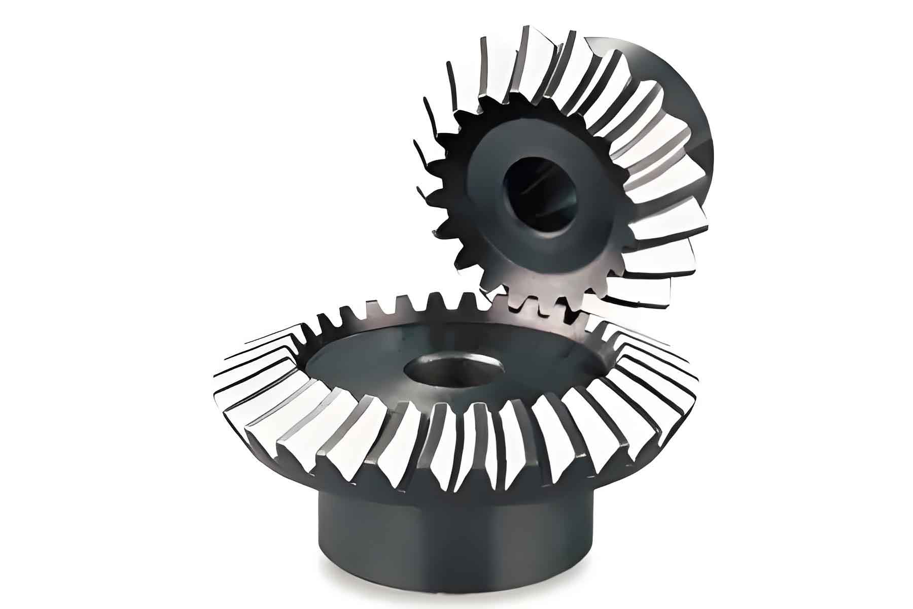
Bevel gear is fundamental components in various mechanical systems, facilitating power transmission between intersecting shafts. The complex geometry and operational demands of bevel gear require precise design and analysis to ensure optimal performance and durability. Finite Element Analysis (FEA) is a powerful computational tool used to model and simulate the behavior of bevel gear under different loading conditions. This article explores the role of FEA in bevel gear design, highlighting its benefits, methodologies, and practical applications.
Importance of FEA in Bevel Gear Design
Finite Element Analysis provides several advantages in the design and optimization of bevel gear:
- Accurate Stress and Strain Analysis:
- Enables detailed evaluation of stress and strain distributions within bevel gear structure, identifying potential failure points.
- Optimization of Gear Geometry:
- Assists in refining bevel gear geometry to enhance performance and efficiency, while reducing material usage and weight.
- Prediction of Operational Behavior:
- Simulates real-world operating conditions to predict bevel gear behavior under various loads, speeds, and environmental factors.
- Cost and Time Efficiency:
- Reduces the need for extensive physical prototyping and testing, saving both time and resources in the development process.
Methodologies in FEA for Bevel Gear
The application of FEA in bevel gear design involves several key steps:
1. Model Creation
- Geometry Definition:
- Create a precise 3D model of the bevel gear, including all relevant features such as teeth profiles, root fillets, and keyways.
- Mesh Generation:
- Discretize the 3D model into a finite number of elements (mesh). A finer mesh provides more accurate results but increases computational requirements.
| Mesh Type | Description | Benefits | Drawbacks |
|---|---|---|---|
| Tetrahedral Mesh | Consists of tetrahedral elements | Suitable for complex geometries | May require more elements for accuracy |
| Hexahedral Mesh | Consists of hexahedral elements | Provides high accuracy with fewer elements | More challenging to generate for complex shapes |
2. Material Properties and Boundary Conditions
- Material Properties:
- Define the material properties of bevel gear, including Young’s modulus, Poisson’s ratio, and yield strength.
- Boundary Conditions:
- Apply appropriate boundary conditions such as fixed supports, loads, and contact conditions between bevel gear teeth.
3. Load Application
- Static Loads:
- Apply static loads to simulate the maximum operational forces acting on bevel gear teeth during normal operation.
- Dynamic Loads:
- Simulate dynamic loads to account for fluctuating forces and torques that occur during bevel gear meshing and rotation.
4. Simulation and Analysis
- Stress and Strain Distribution:
- Analyze the distribution of stress and strain within bevel gear structure to identify high-stress regions and potential failure points.
- Deformation and Deflection:
- Evaluate the deformation and deflection of bevel gear under applied loads to ensure that they remain within acceptable limits.
- Fatigue Analysis:
- Perform fatigue analysis to predict bevel gear’s lifespan under cyclic loading conditions.
Practical Applications of FEA in Bevel Gear Design
1. Strength and Durability Optimization
- Identifying Stress Concentrations:
- FEA helps in locating stress concentrations that may lead to cracks or failure, allowing for design modifications to mitigate these issues.
- Enhancing Material Utilization:
- Optimizing material distribution within bevel gear to achieve the desired strength while minimizing weight and cost.
2. Improving Gear Efficiency
- Tooth Profile Optimization:
- Refining bevel gear tooth profile to reduce friction and improve meshing efficiency, leading to smoother operation and lower energy losses.
- Heat Treatment Simulation:
- Simulating the effects of heat treatment processes to predict changes in material properties and their impact on bevel gear performance.
3. Noise and Vibration Reduction
- Vibration Analysis:
- Assessing bevel gear’s vibrational behavior to identify and mitigate sources of noise and vibration, enhancing the overall performance of bevel gear system.
- Harmonic Response Analysis:
- Conducting harmonic response analysis to understand bevel gear’s response to periodic forces, aiding in the design of quieter gear systems.
Case Study: FEA in High-Performance Automotive Bevel Gear
Background
A high-performance automotive manufacturer aimed to design bevel gear for a new differential system that could withstand high loads and rotational speeds while maintaining efficiency and durability.
FEA Implementation
- Modeling and Meshing:
- Created a detailed 3D model of the bevel gear and generated a hexahedral mesh for accurate analysis.
- Material and Boundary Conditions:
- Defined material properties of high-strength alloy steel and applied realistic boundary conditions based on operational data.
- Load Application:
- Simulated both static and dynamic loads to replicate real-world driving conditions.
- Analysis and Optimization:
- Conducted stress, strain, and deformation analyses to identify and address potential failure points.
- Optimized the tooth profile and material distribution to enhance strength and reduce weight.
Results
- Improved Durability:
- The optimized gear exhibited significantly lower stress concentrations, resulting in a 25% increase in durability.
- Enhanced Efficiency:
- Refined tooth profiles reduced friction and improved meshing efficiency, leading to a 10% improvement in overall bevel gear performance.
- Reduced Noise and Vibration:
- Vibration analysis and harmonic response analysis helped in designing gear with reduced noise and smoother operation.
Future Trends in FEA for Bevel Gear Design
1. Integration with Advanced Manufacturing Techniques
- Additive Manufacturing:
- Combining FEA with additive manufacturing to design and produce complex bevel gear geometries with optimized performance characteristics.
- Smart Materials:
- Utilizing smart materials that can adapt to changing loads and conditions, with FEA aiding in their design and application.
2. Real-Time Simulation and Monitoring
- Digital Twins:
- Developing digital twins of bevel gear systems that use real-time data and FEA simulations to monitor performance and predict maintenance needs.
- AI and Machine Learning:
- Integrating AI and machine learning algorithms with FEA to enhance simulation accuracy and accelerate the design process.
3. Sustainability and Environmental Considerations
- Eco-Friendly Materials:
- Using FEA to explore and optimize the use of environmentally friendly materials in bevel gear design.
- Energy Efficiency:
- Designing gears with FEA to reduce energy consumption and improve overall system efficiency.
Conclusion
Finite Element Analysis is a vital tool in the design and optimization of bevel gear, providing detailed insights into their mechanical behavior under various conditions. By leveraging FEA, engineers can enhance the durability, efficiency, and performance of bevel gear while reducing development time and costs. As technology advances, the integration of FEA with advanced manufacturing techniques, real-time monitoring, and sustainable practices will further revolutionize bevel gear design, ensuring their reliable performance in a wide range of applications.