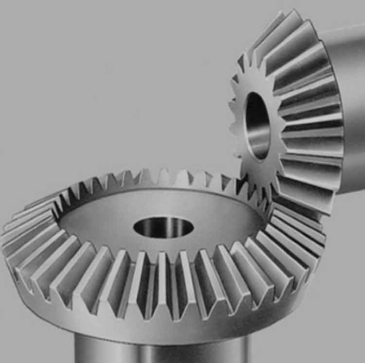
Finite Element Analysis (FEA) is a powerful computational tool used to study and optimize the load distribution in straight bevel gear under variable torque conditions. This analysis helps in understanding the stress and strain behaviors of straight bevel gear, ensuring their reliability and performance in different operating scenarios.
1. Introduction to FEA in Gear Analysis
Purpose of FEA:
- To predict the stress distribution and identify potential failure points.
- To optimize the straight bevel gear design for improved performance and durability.
- To evaluate the effects of variable torque on straight bevel gear load distribution.
Steps in FEA:
- Model creation
- Material property assignment
- Boundary condition application
- Meshing
- Load application
- Result interpretation
2. Model Creation
3D CAD Modeling:
- Use CAD software to create a detailed 3D model of the straight bevel gear.
- Ensure accurate representation of straight bevel gear geometry, including teeth profiles, root fillets, and any keyways or splines.
Material Properties:
- Assign material properties such as Young’s modulus, Poisson’s ratio, and density.
- Include material-specific properties such as hardening behavior if applicable.
3. Meshing
Mesh Generation:
- Use finite element software to generate a mesh for the straight bevel gear model.
- Ensure fine meshing in critical areas like the straight bevel gear teeth and root fillets to capture stress concentrations accurately.
Element Type:
- Use tetrahedral or hexahedral elements depending on the complexity of straight bevel gear geometry.
- Higher-order elements may be used for increased accuracy in critical areas.
4. Boundary Conditions
Fixed Supports:
- Apply fixed support conditions to straight bevel gear hub or shaft connection to simulate realistic constraints.
- Ensure the supports reflect the actual physical constraints in straight bevel gear assembly.
Load Application:
- Apply variable torque conditions to straight bevel gear teeth to simulate operating conditions.
- Use a range of torque values to study the effects of different load levels on straight bevel gear performance.
5. Analysis Under Variable Torque
Static Analysis:
- Perform a static analysis to determine the stress and strain distribution under each torque condition.
- Analyze the results to identify high-stress regions and potential failure points.
Dynamic Analysis:
- For more realistic simulation, perform a transient dynamic analysis to study straight bevel gear behavior under varying torque over time.
- Include effects such as straight bevel gear meshing cycles and load variations.
Load Distribution:
- Evaluate the load distribution across straight bevel gear teeth to understand how torque is transmitted.
- Identify areas with uneven load distribution that may lead to premature wear or failure.
6. Result Interpretation
Stress Analysis:
- Examine the von Mises stress distribution to identify areas with high stress concentrations.
- Compare stress levels under different torque conditions to determine straight bevel gear’s safety factor.
Deformation Analysis:
- Study the deformation patterns to ensure that straight bevel gear maintains its structural integrity under load.
- Check for excessive deformations that could affect straight bevel gear meshing and performance.
Fatigue Analysis:
- Use the stress results to perform a fatigue analysis, predicting straight bevel gear’s lifespan under cyclic loading conditions.
- Identify critical areas where fatigue failure is most likely to occur.
7. Design Optimization
Geometry Optimization:
- Based on the FEA results, optimize straight bevel gear geometry to reduce stress concentrations.
- Modify parameters such as tooth profile, root fillet radius, and straight bevel gear dimensions for improved load distribution.
Material Selection:
- Consider alternative materials with better mechanical properties if current material does not meet performance requirements.
- Evaluate the benefits of advanced materials such as high-strength alloys or composite materials.
Heat Treatment:
- Recommend appropriate heat treatment processes to enhance surface hardness and wear resistance.
- Analyze the effects of heat treatment on residual stresses and overall straight bevel gear performance.
8. Case Study: Variable Torque Conditions
Scenario 1: Low Torque:
- Analyze the load distribution and stress levels at low torque conditions.
- Ensure that straight bevel gear operates within safe stress limits and minimal deformation.
Scenario 2: Medium Torque:
- Study the stress distribution and potential deformation at medium torque.
- Check for any emerging high-stress areas that need attention.
Scenario 3: High Torque:
- Evaluate straight bevel gear performance under high torque conditions.
- Identify critical stress concentrations and areas at risk of failure.
Scenario 4: Torque Fluctuations:
- Simulate real-world conditions with fluctuating torque.
- Analyze straight bevel gear’s response to dynamic loading and identify potential issues.
Conclusion
Finite Element Analysis of load distribution in straight bevel gears under variable torque conditions provides valuable insights into gear performance and durability. By accurately modeling straight bevel gear, applying realistic boundary conditions, and analyzing the results, engineers can optimize gear designs to ensure reliable operation in automotive transmissions. The findings from FEA help in identifying potential failure points, improving material selection, and refining manufacturing processes, ultimately leading to more robust and efficient gear systems.
