
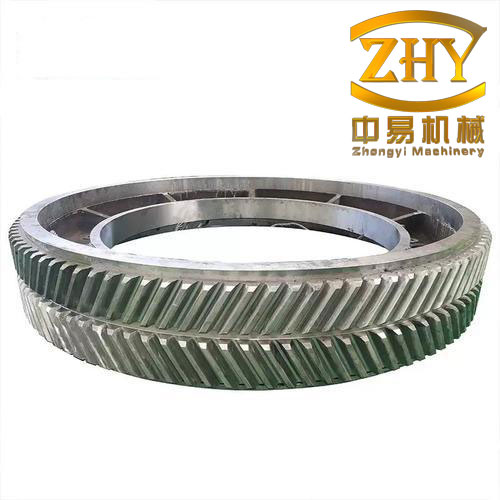
Herringbone gears are among the most critical power-transmission components in heavy-duty rotating machinery. Their characteristic double-helix configuration cancels the axial thrust generated by a single helical gear, while preserving high overlap ratio, smooth meshing, and excellent load-carrying capacity. These attributes make herringbone gears particularly suitable for marine propulsion systems, aerospace gearboxes, and large-scale energy equipment, where reliability under high speed and heavy load is paramount. In my study, I focused on the numerical evaluation of contact strength and bending strength of herringbone gear pairs using the finite element method. The main contribution of my work is the development of a parameterized gear model that includes realistic machining errors, assembly errors, and tooth profile or lead modifications, followed by a systematic finite element contact analysis to quantify their influence on meshing performance.
Although traditional gear design standards such as ISO and AGMA provide empirical formulas for contact and bending stress, these formulas rely on simplified equivalent cylinders and cannot fully account for the complex tooth geometry, load sharing among multiple tooth pairs, and local stress concentrations caused by manufacturing deviations. In contrast, the finite element method is capable of representing the actual tooth flank geometry, contact compliance, and nonlinear boundary conditions with high fidelity. Therefore, I adopted a fully three-dimensional finite element approach to calculate the stress state of herringbone gear pairs under both static and dynamic loading conditions. I also investigated how machining errors and shaft misalignment affect the stress distribution, and finally explored the effectiveness of profile modification and lead crowning in compensating for these adverse effects.
1. Geometric Modeling of Standard Herringbone Gears
The accurate construction of the three-dimensional tooth flank geometry is the prerequisite for a reliable finite element analysis. I generated the tooth surfaces by simulating the enveloping process between a rack cutter and the gear blank. The rack cutter profile is divided into several segments, including the tip, the tip fillet, the involute generating segment, and the modified segment. Each segment is expressed as a parametric curve in the cutter coordinate system, and the corresponding unit normal vectors are derived for the meshing condition.
| Parameter | Symbol | Formula or range |
|---|---|---|
| Helix angle | \(\beta\) | \(0^\circ\) to \(30^\circ\) |
| Normal module | \(m_n\) | Standard value |
| Transverse module | \(m_t\) | \(m_t = m_n / \cos\beta\) |
| Normal pressure angle | \(\alpha_n\) | \(20^\circ\) to \(30^\circ\) |
| Transverse pressure angle | \(\alpha_t\) | \(\tan\alpha_t = \tan\alpha_n / \cos\beta\) |
| Addendum coefficient | \(h_a^*\) | Standard value |
| Clearance coefficient | \(c^*\) | Standard value |
| Profile shift coefficient | \(x_s\) | Standard value |
| Normal base pitch | \(p_n\) | \(p_n = \pi m_n\) |
| Transverse base pitch | \(p_t\) | \(p_t = p_n / \cos\beta\) |
| Fillet radius | \(R\) | \(R \approx 0.2 m_n\) |
| Face width | \(B\) | \(B > 0\) |
| Maximum profile modification | \(\Delta\) | \(> 0\) |
| Crowning amount | \(C_c\) | \(0\) to \(0.001B\) |
| Crowning offset | \(A_l\) | \(0\) to \(0.001B\) |
For the involute generating segment of the rack cutter, the position vector in the cutter section is written as
$$ \mathbf{R}_t^{(eg)}(l_e) = \begin{bmatrix} b_c + l_e \sin\alpha_t + \Delta_{\text{crown}} \cos\alpha_t \\ -l_e \cos\alpha_t + \Delta_{\text{crown}} \sin\alpha_t \\ 0 \\ 1 \end{bmatrix}, $$
where \(l_e\) is the curve parameter and \(\Delta_{\text{crown}}\) is the local crowning amount applied on the cutter. The unit normal vector of this segment is
$$ \mathbf{N}_t^{(eg)} = \begin{bmatrix} \sin\alpha_t \\ -\cos\alpha_t \\ 0 \end{bmatrix}. $$
The transformation from the rack-cutter coordinate system \(S_t\) to the gear coordinate system \(S_1\) is given by the following matrix
$$ M_{1t}(\varphi) = \begin{bmatrix} 1 & 0 & 0 & -\varphi \tan\beta \\ 0 & 1 & 0 & 0 \\ 0 & 0 & 1 & 0 \\ 0 & 0 & 0 & 1 \end{bmatrix}, $$
where \(\varphi\) represents the translation parameter of the rack cutter. The gear rotation angle is related to the cutter translation \(s\) by
$$ s = r_{p1} \phi_{p1}, $$
where \(r_{p1}\) is the pitch radius of the gear and \(\phi_{p1}\) is the rotation angle of the gear blank.
According to the theory of gearing, the enveloping condition requires that the relative sliding velocity between the cutter and the gear blank is orthogonal to the common normal. This leads to the meshing equation
$$ f(l_j, \varphi, \phi_{p1}) = N_x^{(j)} x_1^{(j)} + N_y^{(j)} \left( r_{p1} \phi_{p1} – x_1^{(j)} \right) = 0, \quad j = ac, ce, eg, gs, \ldots $$
Combining the cutter geometry, the coordinate transformation, and the meshing equation, the tooth surface of the generated gear is expressed as
$$ \mathbf{R}_2^{(j)}(l_j, \varphi, \phi_{p1}) = M_{21}(\varphi, \phi_{p1}) \mathbf{R}_1^{(j)}(l_j, \varphi), $$
with the transformation matrix
$$ M_{21}(\varphi, \phi_{p1}) = \begin{bmatrix} \cos\phi_{p1} & \sin\phi_{p1} & 0 & -r_{p1}\cos\phi_{p1} \\ -\sin\phi_{p1} & \cos\phi_{p1} & 0 & r_{p1}\sin\phi_{p1} \\ 0 & 0 & 1 & 0 \\ 0 & 0 & 0 & 1 \end{bmatrix}. $$
I implemented the above equations in MATLAB to compute the discrete tooth-surface points. Then, through a Visual Basic script, I invoked the CATIA macro commands to read the coordinate data and automatically create the three-dimensional solid model of a single gear tooth. By mirroring and patterning the tooth model, I obtained the complete herringbone gear geometry. The herringbone gear consists of two helical gear halves with opposite helix directions, separated by a central recess or run-out groove. A representative three-dimensional model is shown in my thesis. The main design parameters of the herringbone gear pair used in the numerical calculations are listed in Table 2.
| Parameter | Symbol | Value |
|---|---|---|
| Number of teeth | \(z_1 / z_2\) | 31 / 34 |
| Normal module | \(m_n\) | 9 mm |
| Normal pressure angle | \(\alpha_n\) | 25.6° |
| Face width | \(B\) | 90 mm |
| Helix angle | \(\beta\) | 35.98° |
| Material | — | 45 steel |
2. Finite Element Modeling of the Herringbone Gear
Because the herringbone tooth flank has a complex doubly curved surface, generating a high-quality structured hexahedral mesh directly is difficult. I therefore used a domain-decomposition strategy. In CATIA, I divided a single gear tooth into several simple geometric subregions using auxiliary cutting surfaces along the tooth root and the tooth boundary. The segmented solid model was then imported into ABAQUS, where virtual topology operations were used to merge short edges and small faces, so that each subregion could be meshed with structured hexahedral elements.
I selected the linear reduced-integration hexahedral element C3D8R for the discretization. This element type is computationally efficient and sufficiently accurate for contact stress analysis. After meshing a single tooth, I obtained the complete gear mesh by circular patterning and merging. To balance accuracy and computational cost, I refined the mesh only for nine teeth in the meshing zone, while the remaining teeth were meshed with a coarser grid. Two transition teeth were added between the fine and coarse zones to ensure continuous nodal connectivity. The final finite element model contained about 363,986 nodes and 309,776 elements. Figure 2 in my thesis shows the assembled herringbone gear finite element model and a magnified view of the contact region.
| Parameter | Value |
|---|---|
| Elastic modulus \(E\) | 210 GPa |
| Poisson’s ratio \(\nu\) | 0.3 |
| Density \(\rho\) | 7800 kg/m³ |
| Transmitted power \(P\) | 8000 kW |
| Input speed \(n_1\) | 3000 rpm |
| Transmission ratio | 0.91 |
3. Static and Dynamic Contact Analysis
3.1 Analysis Setup
I performed both quasi-static and dynamic contact analyses in ABAQUS. For the static analysis, the outer surface of the gear bore was coupled to a reference point using a kinematic coupling constraint. The driving gear was constrained by fixing all degrees of freedom except the rotation around its axis. A small rotation was initially applied to establish contact, after which the load was gradually increased to the full torque level. The contact between tooth flanks was modeled with a hard normal contact formulation and a penalty friction law with a friction coefficient of 0.06.
For the dynamic analysis, I used the explicit dynamics solver. The same finite element mesh and contact definitions were retained. The driving gear was given a rotational velocity of 1000 rpm, while the driven gear was loaded by a torque of 9545 N·m. Rayleigh damping was introduced to dissipate high-frequency oscillations. The loading time was set to 0.02 seconds.
3.2 Contact Stress and Bending Stress Results
The maximum contact stress and maximum bending stress obtained from the static and dynamic analyses are compared with the empirical gear-design values in Table 4.
| Calculation type | Maximum contact stress (MPa) | Maximum bending stress (MPa) |
|---|---|---|
| Static contact analysis | 570.4 | 137.7 |
| Dynamic contact analysis | 834.2 | 290.3 |
| Gear design handbook | 581.1 | 138.5 |
For the static analysis, the maximum contact stress differs from the handbook value by only 1.8%, and the maximum bending stress differs by only 0.55%. This close agreement confirms the validity of the finite element model. The dynamic analysis produces higher stresses because it accounts for inertial effects, friction, and meshing impacts. During the start of meshing, the contact force exhibits a pronounced impact peak; after this initial transient, the contact force stabilizes to a steady level.
3.3 Contact Force and Contact Area
I extracted the time histories of the contact force on several adjacent tooth pairs. Under static loading, all tooth pairs exhibited essentially the same load history, indicating that the herringbone gear pair distributes load symmetrically between the left-hand and right-hand helical halves. Under dynamic loading, the contact force at the meshing-in and meshing-out positions was significantly higher than the nominal level. This is caused by edge contact and impact when the tooth pair enters or leaves the meshing zone.
The contact area varied in a similar manner. In the static analysis, the contact area increased gradually during the initial meshing period and then reached a stable plateau. In the dynamic analysis, the contact area showed a large spike during the impact phase, followed by a quasi-steady regime. The dynamic contact area was much larger than the static one because the higher dynamic contact force produces a larger elastic deformation of the tooth surfaces.
4. Influence of Machining and Assembly Errors
4.1 Machining Error Model
A herringbone gear is essentially two helical gears manufactured on the same blank. If there is a phase difference between the left-hand and right-hand helical sections, the two halves cannot mesh simultaneously with the mating gear, leading to an uneven distribution of torque along the face width. I simulated this type of machining error by rotating one helical half of the gear model by a small angular offset relative to the other half. Based on typical manufacturing tolerances, I chose machining errors of 10, 20, 30, and 40 μm, which correspond to gear rotation offsets of approximately 0.00625°, 0.0125°, 0.01875°, and 0.025°, respectively.
The static contact analyses were then repeated for each error level. The contact stress contours clearly showed that the machining error affects the load sharing between the left and right helical halves. As the error increases, one helical half carries an increasingly larger portion of the load, while the other half becomes progressively unloaded. The difference in the contact stress and the bending stress between the two halves increases with the error magnitude.
Table 5 summarizes the peak contact force on the left and right halves for different machining errors.
| Machining error (μm) | Left-half peak contact force (N) | Right-half peak contact force (N) |
|---|---|---|
| 10 | 26114 | 18269 |
| 20 | 30008 | 14430 |
| 30 | 33854 | 10572 |
| 40 | 37611 | 6567 |
The results show that the total transmitted load remains nearly constant, but the distribution between the two halves changes dramatically. At a machining error of 40 μm, the right half transmits only about 15% of its ideal share. Such an unbalanced load distribution increases the risk of pitting, scuffing, and tooth fracture on the heavily loaded side. Therefore, the phase accuracy between the two helical halves of a herringbone gear must be strictly controlled during manufacturing.
4.2 Assembly Error Model
In addition to machining errors, assembly errors are almost inevitable in practical gearboxes. The most common assembly error is the non-parallelism of the gear axes, which can be caused by bearing seat misalignment or shaft deflection. I simulated the shaft misalignment by inclining the driving gear axis by an angle \(\theta\) relative to the driven gear axis, as shown schematically in my thesis. The misalignment angles considered were 0.1°, 0.2°, and 0.3°.
The maximum contact stress and bending stress under different assembly errors are listed in Table 6.
| Assembly error (°) | Maximum contact stress (MPa) | Maximum bending stress (MPa) |
|---|---|---|
| 0.1 | 1535 | 657 |
| 0.2 | 1595 | 745 |
| 0.3 | 1696 | 831 |
It is evident that both the contact stress and the bending stress increase monotonically with the misalignment angle. The rate of increase is particularly noticeable for the bending stress, which rises from 657 MPa at 0.1° to 831 MPa at 0.3°, an increase of about 26%. The contact stress increases by about 10% over the same range. This means that axis misalignment is a critical factor that can significantly shorten the fatigue life of herringbone gears. In practice, the parallelism tolerance of the gear shafts should be kept as small as possible.
The stress distribution along the tooth width also becomes strongly non-uniform under misalignment. The contact line is no longer parallel to the tooth root; instead, it is inclined, causing one end of the tooth to carry more load than the other. This is the typical edge-loading phenomenon that can lead to premature tooth breakage.
5. Profile and Lead Modification
5.1 Profile Modification
Profile modification, also known as tip relief, is an effective way to reduce the impact and dynamic load caused by tooth flexibility and manufacturing deviations. The basic idea is to remove a small amount of material from the tooth tip so that the effective base pitch of the gear pair is equalized when the tooth deflects under load. The profile modification curve is usually described by a power function:
$$ e(x) = \Delta_{\max} \left( \frac{x}{l} \right)^b, $$
where \(\Delta_{\max}\) is the maximum modification amount, \(l\) is the modification length, \(x\) is the coordinate measured from the modification start point along the line of action, and \(b\) is the modification curve exponent. I chose a parabolic curve with \(b = 2\), which allows a smooth transition between the modified and unmodified portions of the involute profile.
I generated a series of herringbone gear models with different maximum profile modification amounts, namely 0, 5, 8, 10, 13, 25, 35, and 45 μm. The finite element results are summarized in Table 7.
| Profile modification amount (μm) | Maximum contact stress (MPa) | Tooth-tip contact stress (MPa) |
|---|---|---|
| 0 | 344 | 496 |
| 5 | 345 | 316 |
| 8 | 339 | 305 |
| 10 | 333 | 329 |
| 13 | 356 | 361 |
| 25 | 363 | 401 |
| 35 | 381 | 422 |
| 45 | 417 | 452 |
Without modification, the maximum contact stress occurs near the tooth tip and is about 496 MPa. When an appropriate amount of profile modification is applied, the tooth-tip contact stress is reduced significantly. The most effective modification amount is around 10 μm, which reduces the maximum contact stress to 333 MPa and the tooth-tip stress to 329 MPa. If the modification amount is too small, the tip interference is not fully eliminated. If it is too large, the effective contact ratio decreases and the stress on the remaining part of the profile increases again. Therefore, selecting the optimum modification amount is essential for improving the load-carrying capacity and reducing the sensitivity to manufacturing and assembly errors.
5.2 Lead Crowning
Lead crowning, or drum-shaped modification, is applied along the tooth width direction. It is intended to compensate for shaft bending, torsional deformation, and bearing deflections that cause non-uniform load distribution along the face width. The crowning curve is usually parabolic, with the maximum reduction \(C_c\) at the tooth mid-width and zero reduction at the two ends:
$$ \Delta_c(x_w) = C_c \left( \frac{2x_w}{B} \right)^2, $$
where \(x_w\) is the coordinate along the face width measured from the center of the tooth. I studied five crowning amounts: 5, 10, 15, 20, and 25 μm. The finite element results are given in Table 8.
| Crowning amount (μm) | Maximum contact stress (MPa) | Tooth-tip contact stress (MPa) |
|---|---|---|
| 0 | 344 | 496 |
| 5 | 367 | 561 |
| 10 | 380 | 645 |
| 15 | 454 | 554 |
| 20 | 442 | 749 |
| 25 | 470 | 757 |
The results show that the lead crowning reduces the edge contact at the tooth ends, but it increases the maximum contact stress in the central region of the tooth. This is because crowning reduces the effective contact area, and for a given transmitted load, a smaller contact area leads to a higher average contact pressure. For the studied herringbone gear pair, the crowning did not yield a net improvement in the maximum contact stress. Therefore, the crowning amount must be chosen carefully according to the expected elastic deformation of the shaft system. In applications where shaft misalignment is large, a moderate crowning amount can prevent edge loading and thus prolong the gear life, even though the nominal contact stress is somewhat higher.
5.3 Combined Effect of Modification and Assembly Errors
Because assembly errors cannot always be completely avoided, it is of practical interest to check whether profile modification and lead crowning can compensate for the influence of shaft misalignment. I applied the tested modification schemes to the herringbone gear pair with assembly errors of 0.1° and 0.2°. The combination cases are listed in Table 9.
| Assembly error (°) | Modification scheme |
|---|---|
| 0.1 | No modification / Profile 10 μm / Crowning 10 μm |
| 0.2 | No modification / Profile 10 μm / Crowning 10 μm |
For the assembly error of 0.1°, the profile modification reduced the maximum contact stress at the heavily loaded edge by about 15% compared with the unmodified gear. The lead crowning produced a similar beneficial effect, since it transferred the load away from the tooth edge to the central part of the tooth. For the assembly error of 0.2°, the improvement was still visible, although the absolute stress level remained high due to the severe misalignment.
The combined analysis demonstrates that neither profile modification nor lead crowning can completely eliminate the harmful effect of large assembly errors. Nevertheless, a properly selected modification can substantially reduce the stress concentration and delay the initiation of fatigue cracks. Therefore, in the design and manufacturing of herringbone gears for high-speed and heavy-load applications, it is recommended to adopt both profile modification and lead crowning, and simultaneously to control the shaft parallelism tolerance to a tight level.
6. Conclusions and Future Work
In this thesis, I carried out a comprehensive finite element strength analysis of herringbone gears with machining errors, assembly errors, and tooth modifications. The main conclusions are summarized as follows:
First, I established an accurate parameterized geometric model of herringbone gears based on the enveloping theory of the rack cutter. The three-dimensional solid model was created in CATIA and discretized in ABAQUS using a domain-decomposition technique with structured hexahedral elements. The resulting finite element model successfully reproduced the complex tooth geometry and provided smooth contact stress distributions.
Second, the quasi-static contact analysis of the standard herringbone gear yielded maximum contact and bending stresses of 570.4 MPa and 137.7 MPa, respectively. These values agree with the empirical gear handbook values within 2%, which validates the accuracy of the finite element model. The dynamic analysis, which accounts for impact and friction, produced higher stresses and clearly demonstrated the presence of meshing impact at the beginning and end of the meshing cycle.
Third, the machining error caused by a phase difference between the left and right helical halves has a strong influence on load sharing. As the machining error increases from 10 μm to 40 μm, the contact force on one half increases by 44%, while the contact force on the other half decreases by over 70%. This unbalanced load distribution can seriously reduce the fatigue life of the heavily loaded side.
Fourth, the assembly error caused by non-parallel gear shafts increases both contact and bending stresses significantly. Increasing the misalignment angle from 0.1° to 0.3° raises the maximum contact stress by approximately 10% and the maximum bending stress by approximately 26%. Therefore, the shaft parallelism tolerance is a critical factor affecting the reliability of herringbone gear drives.
Fifth, profile modification with a parabolic curve is effective in reducing the tooth-tip stress and eliminating meshing impact. For the gear pair studied in this work, the optimal profile modification amount is about 10 μm, which reduces the maximum contact stress by approximately 3% and the tooth-tip stress by about 34% compared with the unmodified case. Lead crowning reduces edge loading but increases the nominal contact stress in the central region; it should be used only when significant shaft deflection or misalignment is expected.
Finally, the combination of profile modification and lead crowning can partly compensate for small assembly errors. However, the compensation ability is limited. Hence, both proper modification design and strict assembly quality control are necessary to guarantee the performance and durability of herringbone gear systems.
There are still many factors that have not been fully addressed in the present work. In future studies, I plan to include the effects of shaft and bearing flexibility, housing deformation, thermal expansion, lubrication, and tooth surface roughness on the contact and bending behavior of herringbone gears. Experimental validation using strain-gauge measurements or photoelastic methods will also be carried out to further verify the numerical predictions. The parameterized modeling and finite element analysis framework developed in this thesis can be extended to other gear types and can serve as a powerful tool for the design optimization of high-performance gear transmissions.