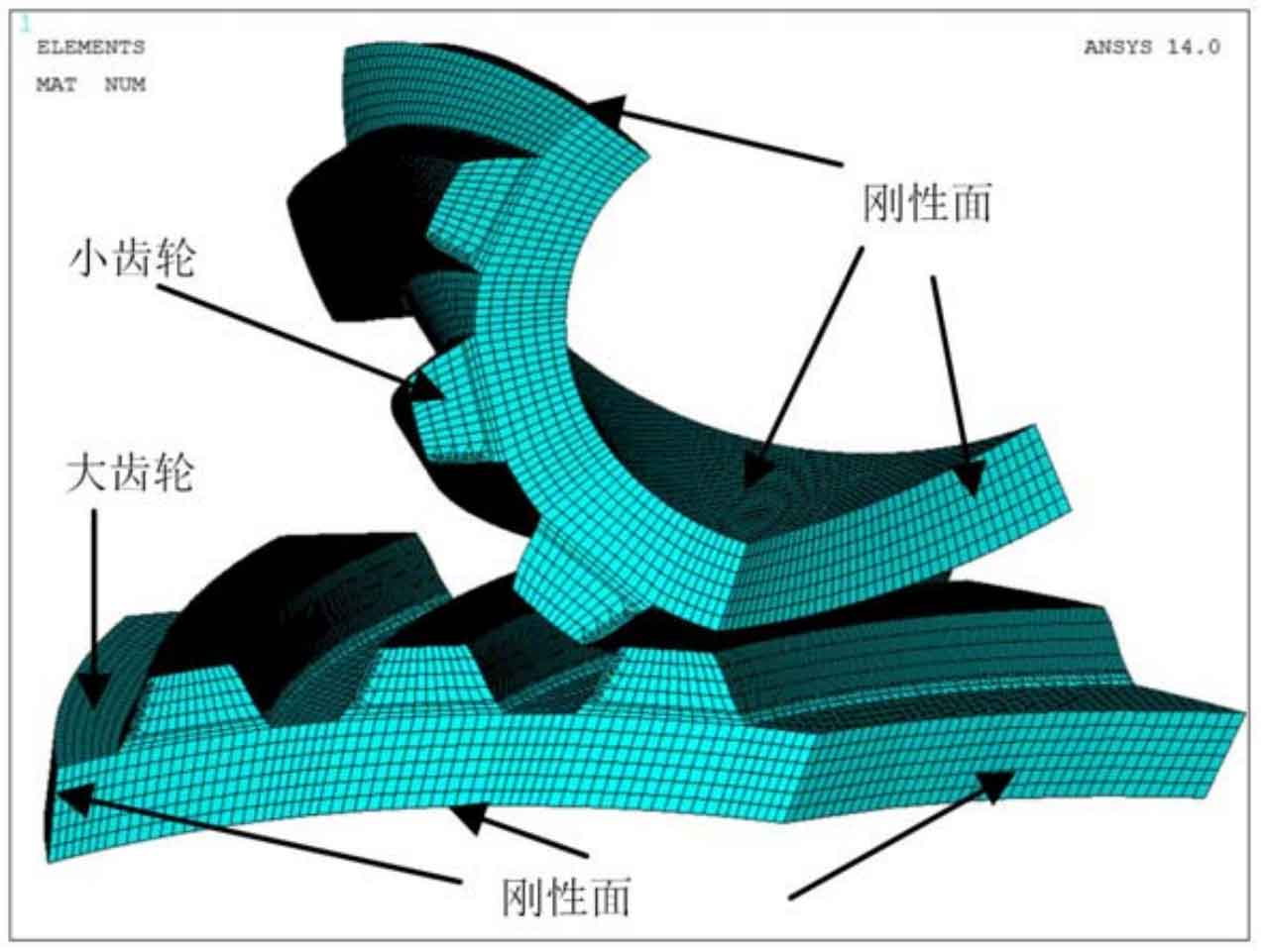
Similarly, the finite element method is still used to analyze the force of pure roll contact long epicycloid bevel gear. For the entity of long epicycloid bevel gear, the low-order hexahedron element solid185 is selected to divide the large and small parts of the grid. Near the contact area, the unit side length of the part participating in the contact tooth surface is set to 0.2mm, and the unit side length of other parts is set to 1-2mm.
The final mesh model is shown in Figure 1. Among them, the binding contact pair based on multi-point constraint algorithm is established between the bottom surface of the large wheel of the long epicycloid bevel gear and the rotation center point, and the binding contact pair based on multi-point constraint algorithm is also established between the inner wall of the small wheel of the long epicycloid bevel gear and the rotation center point. Then 184 elements with their respective rotation axes as kinematic constraints are established for the large and small gears of long epicycloid bevel gear between the rotation center node and the absolute coordinate system. The physical parameter Young’s modulus is 2.05 × 10⁵Mpa, Poisson’s ratio is 0.3. For the boundary load, set the output load to 540nm. Finally, 180 nm input torque is applied to the small wheel of long epicycloid bevel gear, and 0.3 rad / s speed is applied to the large wheel of long epicycloid bevel gear.
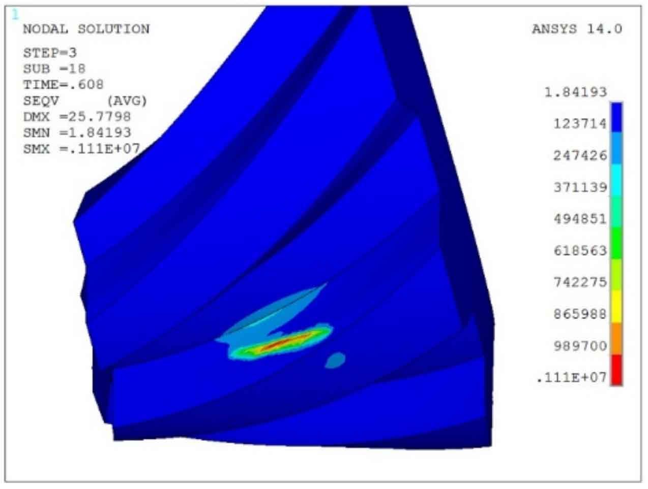
After solving the finite element model, the force distribution of the small wheel and the large wheel of the long epicyclic bevel gear in power transmission can be obtained. Fig. 2 shows the bending and contact stress of the long epicycloid bevel gear pinion when the contact point is located in the middle of the tooth surface. Here, the contact area is still an approximate ellipse.
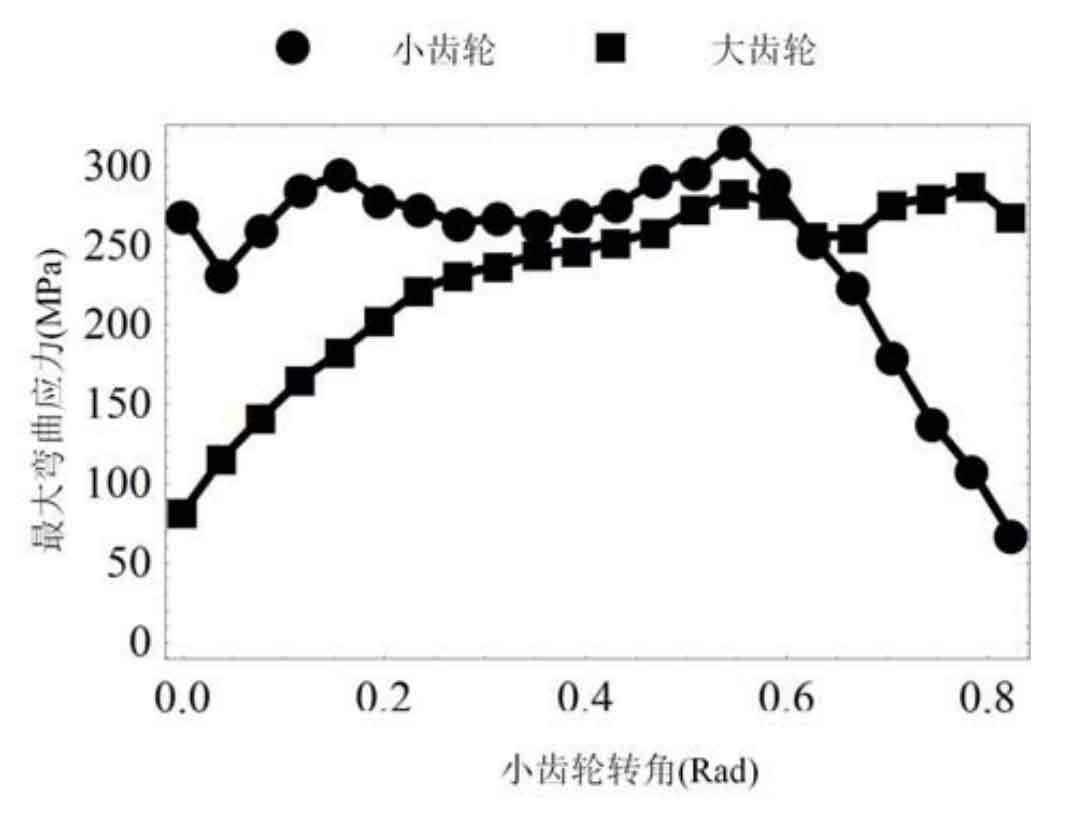
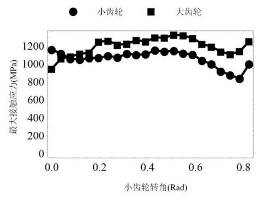
Fig. 3 shows the change of the maximum contact stress of a single tooth in a meshing cycle. It can be seen that the maximum contact stress appears in the middle of the tooth surface, 1290mpa. On both sides along the tooth width direction, the contact stress is relatively reduced because two teeth share the load together.
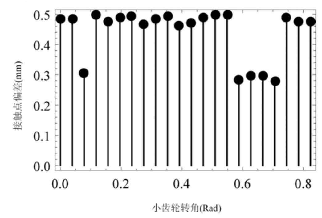
Fig. 4 shows the change of maximum bending stress of single tooth in one meshing cycle, and the maximum bending is 315mpa. For the convenience of analysis, the maximum stress point in the finite element analysis of long epicycloid bevel gear is still set as the qualitative contact point, that is, in the actual meshing process, it is considered that the long epicycloid bevel gear pair contacts at this point.
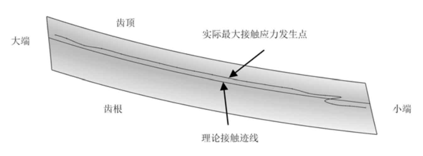
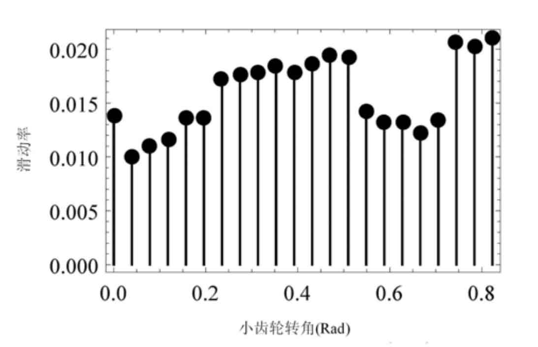
In the meshing process, the absolute value of the deviation between the actual contact point and the ideal contact point of a single tooth in the wired element analysis is shown in Fig. 5 and Fig. 6. Among them, the maximum qualitative contact point position deviation is 0.5mm. Therefore, it can be considered that the actual contact point position is consistent with the theoretical contact point position. At the qualitative contact point, after calculation, in the finite element analysis, the actual sliding rate of the modified long epicycloid bevel gear pair should be as shown in Figure 7. It can be seen that the sliding rate is still maintained at a low level (maximum 0.021).