The tooth profile of the helical gear is involute on the end face, and in the tooth length direction, it looks like an inclined straight line. But it’s actually a helix. Therefore, compared with the teeth of spur gears, the forming of the tooth surface of helical gears is different from the machining of the tooth surface of spur gears only because the shape of the wire is different. Therefore, as long as the forming method of the helix is known, the analysis and processing of the forming method of the tooth surface of the helical gear and its transmission schematic diagram are as simple as the analysis and processing of the straight cylindrical gear.
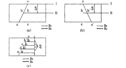
The difference between straight teeth and helical gears in the formation of wires can be illustrated in the figure below.

In figure a, AC is the tooth line of spur gear and AC ‘is the tooth line of helical gear. The right-hand gear shaper is used for gear shaping, which is not shown in the front figure of the workpiece. When the gear shaper is in position I, the cutting point is exactly point a. When the gear shaper tool drops △ s distance (reaches position II), point B of the straight gear tooth to be cut is facing the cutting point of the gear shaper tool. However, if the pinion is a helical gear, the B ‘point needs to be cut. Therefore, it is required that in the process of the straight-line decline of the gear shaper tool △ s, the rotating speed of the workpiece should be faster than that of the gear shaper, that is to say, turn the point to be cut to the point opposite to the gear shaper tool in the current figure.
As the rotation direction (left-hand rotation) of the spiral gear in Fig. B is opposite to that in Fig. a, the rotation speed of the workpiece during machining should be slower than that during slotting the spur gear. The movement direction of the additional rotation of the workpiece is determined by the rotation direction of the gear shaper and the processing gear.
The same explanation can be obtained from figure C. We can imagine that the movement of the gear shaper and workpiece is just like that of the straight cylindrical gear shaper. When the gear shaper lowers a very small distance △ s and cuts out a very thin straight gear, all the movements, one by one, are normalized into motion and axial feed motion, and then the workpiece is given an additional rotation, and the point B ‘is turned to the position of point B, and then, Then cut another slice of spur gear, stop and give the workpiece an additional rotation, turn point C ‘to point C. In this way, the helical gear is like a number of staggered spur gear sheet. If the flakes become thinner, that is, when the movement △ s approaches to 0, the teeth of the helical gear will tend to be continuous. Therefore, as the tool holder moves down, additional rotation B3 shall be added to the workpiece continuously. Since the workpiece should rotate in the forming movement, if additional rotation B3 must also be transmitted to the workpiece, a synthesis mechanism is required in the transmission chain.
