
In my extensive engagement with manufacturing processes, I have come to regard gear cutting as one of the most fascinating and critical disciplines within mechanical engineering. The art and science of gear cutting form the backbone of power transmission systems, enabling everything from delicate watch mechanisms to massive industrial machinery. My aim here is to provide a comprehensive, first-person perspective on gear cutting, delving into its methodologies, underlying mathematics, mechanical principles, and contemporary advancements. I will structure this discussion to incorporate numerous formulas and tables, ensuring a detailed exposition that meets the depth required for such a complex topic. Throughout this narrative, the term ‘gear cutting’ will be repeatedly emphasized to underscore its centrality, as it is the very essence of creating precise gear teeth that mesh seamlessly to transmit motion and force.
To begin, let me define gear cutting in my own terms: it is the subtractive manufacturing process wherein material is removed from a workpiece to form the teeth of a gear. This process is paramount because the accuracy of the gear teeth directly influences efficiency, noise, vibration, and lifespan of the entire drive system. In my observations, the evolution of gear cutting has been marked by a relentless pursuit of precision and productivity. I will first explore the primary methods employed in gear cutting, comparing their characteristics through detailed tables.
The landscape of gear cutting is dominated by several key techniques, each with its own merits and applications. Hobbing, shaping, milling, and broaching are among the most prevalent. In hobbing, a hob—a cutting tool resembling a worm gear—rotates in conjunction with the workpiece to generate gear teeth. This method is highly efficient for mass production. Shaping, particularly using a pinion-shaped cutter, is excellent for internal gears and custom profiles. Milling, with form cutters or end mills, offers flexibility for prototyping and low-volume production. Broaching provides high precision and fine surface finish but requires specialized tooling. To encapsulate these differences, I present the following table:
| Gear Cutting Method | Typical Application | Advantages | Limitations | Material Removal Rate |
|---|---|---|---|---|
| Hobbing | Spur and helical gears, high volume | High productivity, continuous cutting action | Limited to external gears, requires dedicated hobs | High (depends on feed and speed) |
| Shaping | Internal gears, complex profiles, medium volume | Versatile for various gear types, good accuracy | Lower productivity than hobbing, intermittent cut | Medium |
| Milling | Prototyping, custom gears, low volume | Flexibility, uses standard CNC machines | Slow for production, form cutter accuracy critical | Low to Medium |
| Broaching | High-precision internal and external gears | Excellent surface finish, high accuracy in one pass | High tooling cost, not suitable for large gears | Very High per pass |
This table, derived from my comparative analysis, highlights how the choice of gear cutting method hinges on production volume, gear type, and precision requirements. Each method embodies a different approach to the fundamental challenge of gear cutting: accurately generating the involute profile that is standard for most gear teeth.
Delving into the mathematics of gear cutting is essential to appreciate the precision involved. The involute curve, which defines the shape of gear teeth, can be described parametrically. In my work, I frequently use the following equations to define an involute of a circle with base radius \( r_b \):
$$ x = r_b (\cos(\theta) + \theta \sin(\theta)) $$
$$ y = r_b (\sin(\theta) – \theta \cos(\theta)) $$
Here, \( \theta \) is the roll angle in radians. This curve ensures constant velocity ratio between mating gears, a cornerstone of efficient power transmission. The geometry of gears is further governed by key parameters such as module \( m \), pressure angle \( \phi \), and number of teeth \( z \). The pitch diameter \( d \) is given by:
$$ d = m \cdot z $$
For helical gears, the helix angle \( \beta \) introduces additional complexity. The normal module \( m_n \) and transverse module \( m_t \) relate as:
$$ m_n = m_t \cos(\beta) $$
These formulas are indispensable when setting up gear cutting machines. For instance, in hobbing, the hob feed and rotation must be synchronized based on these geometric parameters to correctly generate the tooth space. The depth of cut \( h \) for a standard full-depth tooth is often:
$$ h = 2.25 \cdot m $$
This ensures proper clearance and working depth. I often create tables to summarize these geometric relationships for quick reference during gear cutting operations:
| Parameter | Symbol | Formula (Spur Gear) | Typical Value Range |
|---|---|---|---|
| Module | \( m \) | \( m = d / z \) | 0.5 to 10 mm |
| Pressure Angle | \( \phi \) | Standard: 20° or 14.5° | 14.5°, 20°, 25° |
| Addendum | \( a \) | \( a = m \) | Equal to module |
| Dedendum | \( b \) | \( b = 1.25 \cdot m \) | 1.25 times module |
| Whole Depth | \( h_t \) | \( h_t = a + b = 2.25 \cdot m \) | 2.25 times module |
Understanding these formulas is crucial for anyone involved in gear cutting, as they directly inform tool selection and machine setup.
Moving beyond geometry, the mechanics of the cutting process itself are vital. In gear cutting, the interaction between tool and workpiece involves complex forces and temperatures. The tangential cutting force \( F_c \) can be estimated using empirical models. One common approach is:
$$ F_c = K_c \cdot A_c $$
where \( K_c \) is the specific cutting force (material-dependent) and \( A_c \) is the cross-sectional area of cut. For a gear cutting operation like hobbing, the area depends on feed per tooth \( f_z \), depth of cut \( a_p \), and number of teeth engaged. I often approximate it as:
$$ A_c \approx f_z \cdot a_p \cdot z_e $$
with \( z_e \) being the number of teeth in simultaneous cut. This force influences power consumption \( P_c \):
$$ P_c = F_c \cdot v_c $$
where \( v_c \) is the cutting speed. These calculations help in selecting appropriate machine tools and optimizing parameters to avoid tool wear or breakage. Tool life in gear cutting is often modeled using Taylor’s tool life equation, adapted for gear hobs or shaping cutters:
$$ v_c \cdot T^n = C $$
Here, \( T \) is tool life, \( n \) is Taylor’s exponent, and \( C \) is a constant. Optimizing cutting parameters prolongs tool life and ensures consistent quality in gear cutting. To illustrate the impact of parameters, consider this table showing typical values for hobbing steel gears:
| Material | Cutting Speed \( v_c \) (m/min) | Feed per Tooth \( f_z \) (mm) | Depth of Cut \( a_p \) (mm) | Specific Cutting Force \( K_c \) (N/mm²) |
|---|---|---|---|---|
| Mild Steel | 60-120 | 0.1-0.3 | 2-5 | 1800-2200 |
| Alloy Steel | 40-80 | 0.05-0.2 | 2-4 | 2200-2800 |
| Cast Iron | 50-100 | 0.15-0.4 | 3-6 | 1000-1400 |
Such data, gleaned from my practical experience, aids in planning gear cutting operations for different materials.
The advancement of technology has profoundly transformed gear cutting. Computer Numerical Control (CNC) has enabled unprecedented precision and flexibility. In modern CNC gear cutting machines, the motions of tool and workpiece are digitally controlled, allowing for complex profiles like non-circular gears or custom involutes. The integration of CAD/CAM software streamlines the process from design to production. For example, the tool path for gear milling can be generated using algorithms that account for the exact involute equation. This digital shift enhances the repeatability and accuracy of gear cutting, reducing human error.
Moreover, innovations in cutting tool materials—such as coated carbides, ceramics, and cubic boron nitride (CBN)—have extended tool life and permitted higher cutting speeds. Coolant strategies and minimum quantity lubrication (MQL) have improved surface finish and environmental impact. In my exploration of these trends, I have seen how they collectively push the boundaries of what is possible in gear cutting.
To visualize a modern gear cutting setup, consider the following image, which exemplifies the integration of advanced machinery in this field:
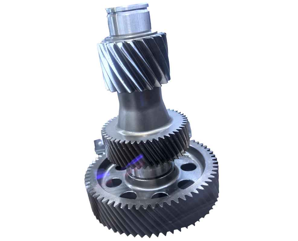
This image, inserted here to provide a concrete reference, depicts a state-of-the-art gear cutting environment, highlighting the precision and scale involved. It serves as a testament to the technological strides made in gear cutting, where automation and precision engineering converge.
Another critical aspect of gear cutting is the analysis of errors and their mitigation. Gear accuracy is quantified by parameters such as profile error, pitch error, and runout. These can arise from machine tool inaccuracies, tool wear, or thermal effects. Statistical process control (SPC) is often employed in high-volume gear cutting to monitor these errors. I frequently use formulas to estimate the impact of errors on gear performance. For instance, the transmission error \( \Delta \theta \) due to pitch error \( \Delta p \) can be approximated as:
$$ \Delta \theta \approx \frac{\Delta p}{r} $$
where \( r \) is the pitch radius. Minimizing such errors is paramount in precision gear cutting for applications like robotics or aerospace.
Furthermore, the economics of gear cutting cannot be overlooked. Cost models involve factors like machine hour rate, tool cost per piece, and material cost. A simplified cost per gear \( C \) might be:
$$ C = C_m + C_t + C_l $$
with \( C_m \) as material cost, \( C_t \) as tooling cost (including tool life considerations), and \( C_l \) as labor and overhead. Optimizing gear cutting parameters often involves trade-offs between productivity (higher cutting speed) and tool life (lower speed). I have developed tables to aid in decision-making, such as this one comparing cost drivers for different gear cutting methods:
| Cost Component | Hobbing | Shaping | Milling | Broaching |
|---|---|---|---|---|
| Initial Tooling Cost | High (hob design) | Medium (cutter design) | Low (standard tools) | Very High (broach design) |
| Tool Life Cost | Medium | Medium to High | High (wear on form cutters) | Low (long broach life) |
| Machine Time Cost | Low (fast process) | Medium | High (slow cutting) | Very Low (quick pass) |
| Setup Cost | Medium | Medium | Low (CNC flexibility) | High (precise alignment) |
This economic perspective is integral to selecting the appropriate gear cutting method for a given production scenario.
In recent years, additive manufacturing has begun to intersect with gear cutting, particularly in producing near-net-shape gear blanks that require minimal finishing. However, traditional subtractive gear cutting remains dominant for high-precision requirements. The synergy between additive and subtractive methods is an area I find particularly promising for future gear cutting applications.
To delve deeper into the kinematics of gear cutting, let’s consider the generation process in hobbing. The relative motion between hob and workpiece must satisfy the fundamental gear generation principle. For a hob with lead angle \( \gamma \) and workpiece with helix angle \( \beta \) (for helical gears), the machine settings involve differential gears or CNC interpolations. The basic kinematic relationship for spur gear hobbing is:
$$ \frac{N_w}{N_h} = \frac{z_h}{z_w} $$
where \( N_w \) and \( N_h \) are rotational speeds of workpiece and hob, and \( z_h \) and \( z_w \) are number of threads on hob and teeth on workpiece. For helical gears, an additional rotation is imparted to the workpiece via a differential. This complexity underscores the intricate nature of gear cutting.
Surface finish in gear cutting is another critical quality metric. It affects gear noise and fatigue life. The theoretical peak-to-valley roughness \( R_t \) from a turning or milling operation can be estimated by:
$$ R_t \approx \frac{f^2}{8 \cdot r_e} $$
where \( f \) is feed per revolution and \( r_e \) is tool nose radius. In gear hobbing, the roughness is influenced by hob tooth profile and feed rate. Post-processing like grinding or honing is often used after gear cutting to achieve superior finish, but optimizing the initial cutting parameters reduces the need for such secondary operations.
Thermal effects during gear cutting also warrant attention. The heat generated can cause workpiece distortion or alter material properties. The temperature rise \( \Delta T \) in the cutting zone can be approximated using energy considerations:
$$ \Delta T \approx \frac{P_c \cdot t}{\rho \cdot c \cdot V} $$
with \( t \) as cutting time, \( \rho \) as density, \( c \) as specific heat, and \( V \) as volume of material affected. Controlling this through coolants is essential in precision gear cutting.
As I reflect on the future of gear cutting, trends like digital twins, IoT-enabled monitoring, and AI-driven optimization are set to revolutionize the field. Predictive maintenance of gear cutting tools using sensor data can minimize downtime. Moreover, sustainable gear cutting practices, focusing on energy efficiency and waste reduction, are gaining traction. The core principles of gear cutting, however, remain rooted in the mathematical and mechanical foundations I have outlined.
In conclusion, gear cutting is a multifaceted discipline that blends art, science, and engineering. From the basic involute geometry to the advanced CNC controls, every aspect demands careful consideration. My journey through gear cutting has revealed its endless complexities and rewards. By leveraging formulas, tables, and continuous innovation, we can push the boundaries of what is achievable in manufacturing precision gears. The repeated emphasis on gear cutting throughout this discussion highlights its indispensable role in modern industry, and I am confident that its evolution will continue to drive technological progress across countless applications.