
Introduction
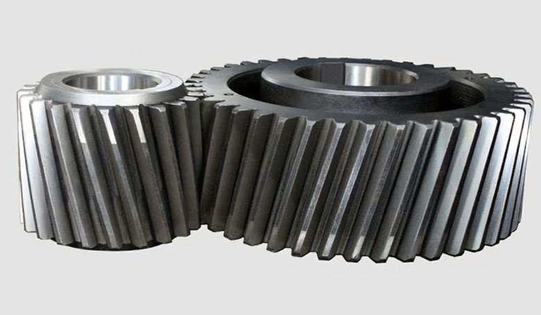
Helical gears are a type of mechanical power transmission system that belongs to the family of gears. They are widely used to transfer rotational motion and power between parallel shafts. Helical gears are an evolution of spur gears, featuring angled teeth that create a helix shape on the gear surface.
Here’s an introduction to helical gears, their characteristics, and their applications:
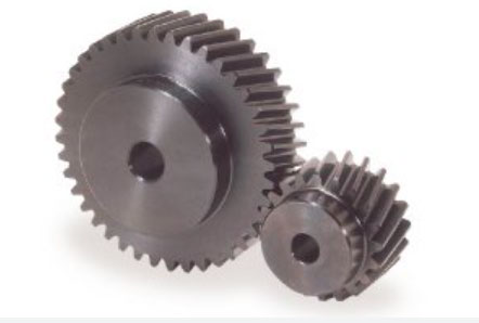
- Teeth Profile: Unlike spur gears with straight teeth, helical gears have teeth that are cut at an angle to the gear axis, forming a helix shape. This angled tooth profile allows for gradual and smooth engagement, resulting in reduced noise and vibration compared to spur gears.
- Parallel Shaft Configuration: Helical gears are designed to operate on parallel shafts, similar to spur gears. They are widely used in applications where motion and power need to be transmitted between parallel shafts.
- Helix Angle: The helix angle is the angle between the tooth helix and the gear axis. It defines the direction of the helix and affects the gear’s performance characteristics. Helix angles can be either right-handed (clockwise) or left-handed (counterclockwise).
- Load Distribution: The helix angle allows for more teeth to be in contact simultaneously during gear engagement compared to spur gears. This leads to better load distribution along the tooth surfaces, enhancing the gear’s load-carrying capacity and overall efficiency.
- Axial Thrust: One drawback of helical gears is the axial thrust they produce due to the helix angle. This thrust tends to push the gear along the shaft. To counteract this effect, helical gears are often used in pairs with opposite helix angles, canceling out the axial forces.
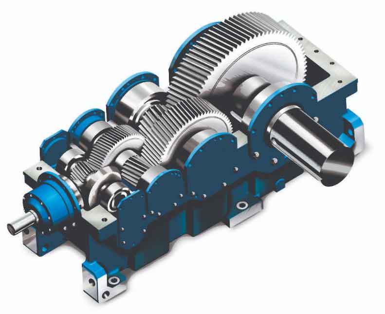
- Applications: Helical gears are used in a wide range of applications, including automotive transmissions, industrial machinery, power generation equipment, printing presses, and more. They are particularly suitable for high-speed and high-load applications where smooth operation and efficiency are essential.
- Efficiency: While helical gears generally have higher efficiency than worm gears, they may still exhibit lower efficiency compared to spur gears, especially at higher helix angles.
- Manufacturing: Helical gears are more challenging to manufacture than spur gears due to the angled tooth profile. Specialized gear cutting processes, such as hobbing or shaping, are used to produce helical gears.
- Noise and Vibration: Helical gears generate less noise and vibration compared to spur gears because the gradual tooth engagement spreads the load more evenly and reduces impact forces.
- Lubrication: Proper lubrication is essential for helical gears to minimize friction and wear. Lubricants help ensure smooth operation and extend the gear’s service life.
In summary, helical gears offer several advantages over spur gears, including improved load distribution, reduced noise, and smoother engagement. However, they require careful design and consideration of axial thrust, manufacturing complexity, and lubrication requirements to optimize their performance for specific applications.
Chapter 1: The characteristics of Helical Gears
Helical gears exhibit several important characteristics that set them apart from other types of gears. These characteristics contribute to their widespread use in various industrial and mechanical applications. Here are the key characteristics of helical gears:
- Helix Angle: The most distinguishing feature of helical gears is the helix angle, which refers to the angle between the tooth helix and the gear axis. This angle allows for a gradual engagement of the gear teeth, resulting in smoother and quieter operation compared to spur gears.
- Parallel Shaft Configuration: Helical gears are designed to transmit motion and power between parallel shafts. Their helical teeth mesh along the gear’s length, enabling efficient transfer of rotational force.
- Load Distribution: Due to the helix angle, helical gears have multiple teeth in contact simultaneously during engagement. This leads to better load distribution along the tooth surfaces, enhancing the gear’s load-carrying capacity and overall efficiency.
- Efficiency: Helical gears generally have higher efficiency than worm gears and bevel gears. Although they may exhibit slightly lower efficiency than spur gears, especially at high helix angles, their overall efficiency is favorable for many applications.
- Axial Thrust: The helix angle generates an axial thrust force that tends to push the gears along the shaft. To counteract this effect, helical gears are often used in pairs with opposite helix angles, canceling out the axial forces.
- Smooth and Quiet Operation: The gradual engagement of helical gear teeth reduces impact forces, resulting in smoother operation with minimal noise and vibration. This feature makes helical gears suitable for applications where noise reduction is essential.
- Overlapping Contact: Helical gears have a longer contact ratio than spur gears. The teeth make contact gradually and overlap, allowing for a more continuous transfer of motion and power.
- Direction of Rotation: Helical gears can be designed with right-handed (clockwise) or left-handed (counterclockwise) helix angles, making them versatile for various rotational directions.
- Manufacturing Complexity: Helical gears are more challenging to manufacture than spur gears due to the angled tooth profile. They require specialized gear cutting processes, such as hobbing or shaping, which can add to production costs.
- Lubrication: Proper lubrication is crucial for helical gears to reduce friction and wear between the tooth surfaces. Adequate lubrication ensures smooth operation and extends the gears’ service life.
Helical gears offer a balance of efficiency, smooth operation, and load-carrying capacity, making them a popular choice for a wide range of applications. Their design considerations include helix angle, axial thrust, lubrication, and manufacturing complexity, which need to be carefully evaluated to optimize their performance in specific use cases.
Chapter 2: Helical Gears, How They Work
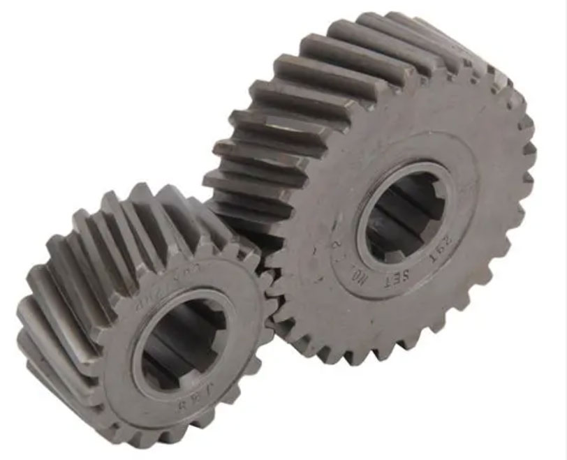
Helical gears are a type of cylindrical gears that have helical teeth with a helix angle. Unlike spur gears, which have straight teeth that are parallel to the gear axis, helical gears have teeth that are cut at an angle to the gear axis. The helix angle causes the teeth to form a helix shape around the gear, similar to the threads of a screw.
Here’s how helical gears work:
- Meshing of Teeth: When two helical gears with parallel axes come in contact, their teeth mesh gradually and smoothly due to the helix angle. This gradual engagement results in less shock and vibration compared to spur gears, making helical gears operate more quietly.
- Power Transmission: As one gear (the driver) rotates, its helical teeth come into contact with the helical teeth of the other gear (the driven gear). The contact between the teeth causes the driven gear to rotate in the opposite direction.
- Axial Thrust: One characteristic of helical gears is the generation of axial thrust. The helix angle creates an axial force that tends to push the gears apart along the gear axis. To counteract this thrust, helical gears are often mounted with thrust bearings or designed with a helix angle that generates balancing axial forces.
- Efficiency: Helical gears are more efficient than spur gears due to the gradual engagement of teeth, which results in less sliding and friction. This leads to improved power transmission efficiency.
- Load Distribution: The helical tooth profile allows for a larger area of contact between the gears, distributing the load more evenly across the teeth. This increased contact area improves the load-carrying capacity of helical gears.
- Direction of Rotation: Helical gears can be designed for both parallel shafts (parallel helical gears) and intersecting shafts (crossed helical gears). In parallel helical gears, the helix angles of both gears are the same, resulting in the same direction of rotation. In crossed helical gears, the helix angles are different, leading to perpendicular shafts and opposite directions of rotation.
Helical gears are commonly used in various applications, such as automotive transmissions, industrial machinery, and power transmission systems. Their smooth operation, improved load distribution, and efficiency make them well-suited for a wide range of mechanical systems. However, their design complexity and axial thrust consideration should be taken into account during gear system design.
Chapter 3: How to Selected Helical Gears
Selecting the right helical gears for a specific application requires careful consideration of various factors to ensure optimal performance and efficiency. Here are the steps to help you select the appropriate helical gears:
- Determine Application Requirements: Understand the specific requirements of your application, including the speed and torque requirements, load conditions, duty cycle, and operating environment. Identify whether the gears will be used for power transmission, speed reduction, or motion control.
- Calculate Gear Parameters: Calculate the required gear parameters, such as gear ratio, pitch diameter, face width, and module (pitch) size based on the application requirements. The gear ratio determines the speed reduction or increase, while the pitch diameter and face width affect the torque-carrying capacity.
- Helix Angle Selection: Choose the appropriate helix angle for the gears. A higher helix angle results in smoother and quieter operation but may generate more axial thrust. Consider the effect of the helix angle on gear efficiency, axial thrust, and load distribution.
- Material Selection: Select the right material for the gears based on the application requirements. Common materials for helical gears include alloy steels, stainless steels, and non-ferrous materials like bronze. Consider factors such as strength, wear resistance, and compatibility with lubricants.
- Lubrication and Cooling: Determine the lubrication requirements for the gear system. Proper lubrication is essential to reduce friction and wear between the gear teeth. Consider whether any cooling provisions are necessary to dissipate heat generated during gear operation.
- Backlash and Tolerance: Consider the desired level of backlash (clearance between gear teeth) and gear tolerances. Lower backlash results in improved accuracy but may require more precise manufacturing and assembly.
- Load Distribution and Strength: Evaluate the load distribution and the strength of the gear teeth. Helical gears distribute loads over multiple teeth, resulting in improved load-carrying capacity. Ensure that the gears can handle the expected loads without premature failure.
- Efficiency and Noise: Assess the gear system’s efficiency and noise level. Helical gears generally offer higher efficiency compared to spur gears, but the helix angle may impact gear efficiency and noise characteristics.
- Quality and Manufacturer: Choose a reputable gear manufacturer that adheres to industry standards and quality control processes. High-quality manufacturing ensures gears with precise dimensions and tooth profiles.
- Application Constraints: Consider any space constraints, weight limitations, or special environmental conditions that may impact gear selection.
By carefully evaluating these factors and consulting with experienced gear designers or manufacturers, you can select the most suitable helical gears that meet your application requirements and provide reliable and efficient performance.
Chapter 4: Manufacturing Process of Helical Gears
The manufacturing process of helical gears involves several steps to create accurate and high-quality gears. Here is an overview of the typical manufacturing process:
- Material Selection: The process begins with selecting the appropriate material for the gears based on their intended application. Common materials for helical gears include alloy steels, stainless steels, and non-ferrous materials like bronze.
- Gear Blank Preparation: The selected material is cut or forged into a gear blank, which is a cylindrical piece of metal with the approximate size and shape of the final gear.
- Gear Cutting: The gear teeth are cut into the gear blank using various methods, such as hobbing, shaping, or milling. Hobbing is the most common method for mass production of helical gears. In hobbing, a special cutting tool called a hob is used to generate the gear teeth by gradually cutting into the gear blank as it rotates.
- Heat Treatment: After cutting, the gears undergo heat treatment processes such as carburizing, quenching, and tempering to enhance their hardness, strength, and wear resistance.
- Tooth Profile Finishing: To ensure the accuracy and smooth operation of the gears, the tooth profiles are finished by grinding or lapping. Grinding removes any remaining imperfections and achieves precise tooth dimensions.
- Gear Inspection: The finished gears are carefully inspected using various measurement techniques to ensure that they meet the required specifications and quality standards.
- Surface Treatment: Depending on the application and requirements, the gears may undergo surface treatments such as shot peening, nitriding, or coating to improve their surface hardness and wear resistance.
- Assembly: If the gear system requires multiple gears to work together, the individual gears are assembled onto their respective shafts to form the complete gear assembly.
- Balancing and Dynamic Testing: For high-precision applications, the gear assemblies may undergo balancing and dynamic testing to minimize vibration and ensure smooth operation.
- Final Quality Inspection: The fully assembled gear systems undergo a final quality inspection to verify their performance, noise level, and overall functionality.
It’s essential to use precise machinery, skilled operators, and quality control measures throughout the manufacturing process to produce helical gears that meet the required specifications and ensure reliable performance in various applications. Additionally, advanced manufacturing technologies, such as computer numerical control (CNC) machining, have significantly improved the accuracy and efficiency of helical gear production.
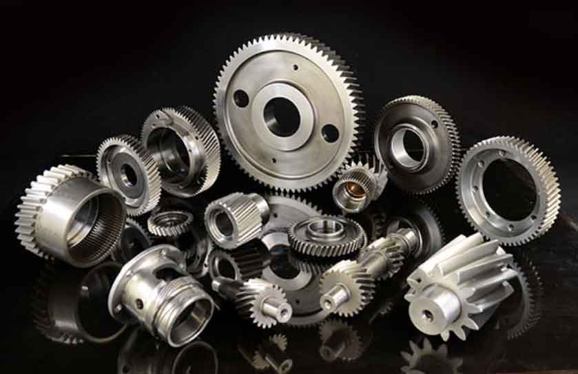
Chapter 5: Types of Helical Gears
Helical gears can be classified into different types based on their design and configuration. Here are the main types of helical gears:
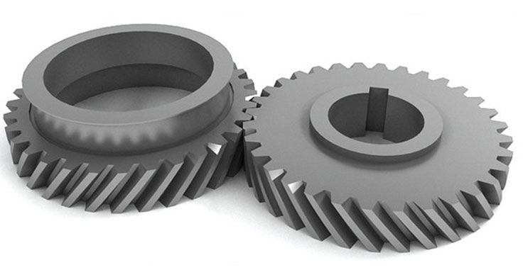
- Parallel Helical Gears: In parallel helical gears, the axes of the gear and the pinion are parallel to each other. They are widely used for power transmission between parallel shafts.
- Crossed Helical Gears (Screw Gears): Crossed helical gears have their axes positioned at an angle to each other. They are used for applications where the shafts are non-parallel and intersect at a point.
- Double Helical Gears (Herringbone Gears): Double helical gears have two sets of teeth that are cut in opposite helix directions on the same gear. The design helps to cancel out axial thrust forces and minimize vibrations, making them suitable for high-load and high-speed applications.
- Skew Helical Gears (Helix Skew Gears): Skew helical gears have teeth that are helically twisted or skewed. This design allows for more gradual tooth engagement and smoother operation.
- Zerol Helical Gears: Zerol helical gears are similar to standard helical gears, but the teeth are cut at a helix angle of zero degrees. This results in teeth with straight sides, similar to spur gears. Zerol helical gears are quieter and smoother than standard helical gears but may have reduced load-carrying capacity.
- Ground Helical Gears: Ground helical gears are precision-machined gears with a high degree of accuracy and surface finish. They are commonly used in applications that require strict tolerances and minimal noise.
- Non-Throated Helical Gears: Non-throated helical gears have no groove (throat) around the gear shaft. They are suitable for light-duty applications.
- Throated Helical Gears: Throated helical gears have a groove or a throat around the gear shaft. This design allows for better lubrication and reduces friction, resulting in higher efficiency and load-carrying capacity.
Each type of helical gear offers specific advantages and is suitable for different applications based on the gear system’s requirements, load capacity, speed reduction, and axial thrust considerations. The selection of the right type of helical gear depends on the specific needs of the gear system and the intended application.
Chapter 6: The Advantages and Disadvantages of Helical Gears
Helical gears offer several advantages and disadvantages compared to other types of gears. Here are some of the key advantages and disadvantages of helical gears:
Advantages:
- Smooth and Quiet Operation: The gradual engagement of helical gear teeth results in smooth and quiet operation, making helical gears less noisy than spur gears.
- High Efficiency: Helical gears have higher efficiency compared to spur gears due to their rolling contact, which reduces friction and power loss.
- Increased Load-Carrying Capacity: The helical tooth profile allows for multiple teeth to be in contact simultaneously, distributing the load over a larger surface area and enhancing the load-carrying capacity of the gears.
- Versatility: Helical gears can be used in various configurations, such as parallel shafts, crossed shafts, and double helical (herringbone) designs, making them versatile for different applications.
- Higher Speed Ratios: Helical gears can achieve higher speed reduction or increase ratios in a single stage compared to spur gears.
- Self-Aligning Capability: Helical gears have a self-aligning capability that helps reduce tooth wear and ensures better gear meshing.
- Efficient Power Transmission: Helical gears are widely used for power transmission in industrial machinery, automotive transmissions, and other mechanical systems.
Disadvantages:
- Axial Thrust: The helix angle in helical gears generates axial thrust along the gear axis, which requires additional thrust bearings or other mechanisms to counteract the force.
- Complex Manufacturing: The manufacturing process of helical gears is more complex and time-consuming compared to spur gears due to the need for helical cutting.
- Increased Friction and Heat Generation: Helical gears may produce more heat due to the sliding contact between gear teeth, leading to potential efficiency loss.
- Backlash: Helical gears can have higher levels of backlash compared to spur gears, affecting positioning accuracy in some applications.
- Radial Load: The helical angle may introduce radial loads, which could require more robust shaft and bearing designs to handle the loads.
- Cost: The complexity of manufacturing and additional features like thrust bearings can make helical gears more expensive compared to spur gears.
Despite these disadvantages, helical gears are widely used in various applications due to their smooth operation, high efficiency, and load-carrying capacity. Engineers must carefully consider the advantages and disadvantages of helical gears when selecting the appropriate gear type for specific applications.
Chapter 7: The Applications of Helical Gears
Helical gears are used in a wide range of applications across various industries due to their unique characteristics and advantages. Some of the common applications of helical gears include:
- Automotive Transmissions: Helical gears are widely used in automotive manual transmissions to provide smooth and efficient gear shifting.
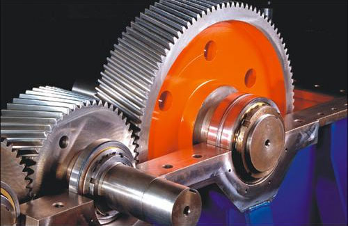
- Industrial Machinery: Helical gears are employed in various industrial machinery, including pumps, compressors, conveyors, and machine tools, for power transmission and motion control.
- Power Generation: Helical gears are used in power generation applications, such as wind turbine gearboxes, to convert rotational motion into electrical power.
- Marine Propulsion: Helical gears are utilized in marine propulsion systems to transfer power from the engine to the propeller shaft.
- Mining Equipment: Helical gears are used in mining equipment, such as crushers and conveyors, to handle heavy loads and provide reliable power transmission.
- Printing Machinery: Helical gears are used in printing machines to control paper feed and other mechanical movements.
- Textile Machinery: Helical gears are employed in textile machinery for various functions, such as controlling yarn tension and thread guidance.
- Aerospace and Defense: Helical gears find applications in aerospace and defense equipment, such as aircraft actuators, weapon systems, and flight control mechanisms.
- Robotics: Helical gears are used in robotics for precise motion control and positioning of robot arms and manipulators.
- Machine Tools: Helical gears are utilized in machine tools for accurate positioning and control of tool movements.
- Material Handling Equipment: Helical gears are used in material handling equipment, such as forklifts and cranes, to handle heavy loads.
- Packaging Machinery: Helical gears are employed in packaging machinery to control the movement and positioning of packaging materials.
- Construction Equipment: Helical gears are used in construction equipment, such as bulldozers and excavators, for efficient power transmission.
- Medical Equipment: Helical gears find applications in medical equipment for precise motion control and positioning in medical devices and imaging equipment.
- Renewable Energy Systems: Helical gears are used in renewable energy systems, such as solar tracking systems and hydropower turbines, to convert natural forces into usable energy.
These are just a few examples of the diverse applications of helical gears in various industries. Helical gears’ ability to provide smooth, efficient, and reliable power transmission makes them a popular choice in a wide range of mechanical systems and equipment.
Chapter 8: Helical Gear Machining
Helical gear machining involves the process of creating helical gears from raw materials using various machining techniques. The specific machining method depends on factors such as the gear’s size, material, precision requirements, and production volume. Here are the common methods used for helical gear machining:
- Hobbing: Hobbing is the most common and efficient method for mass-producing helical gears. In this process, a gear hob (a cutting tool with helical teeth) is used to cut the gear teeth into the gear blank as it rotates. The hob’s helix angle generates the desired helical tooth profile.
- Gear Shaping: Gear shaping is another popular method for helical gear manufacturing, especially for larger gears or those requiring high precision. In gear shaping, a gear-shaped cutting tool called a shaper cutter is used to generate the gear teeth on the gear blank.
- Gear Grinding: Gear grinding is a precision machining process used to achieve high accuracy and surface finish on helical gears. After hobbing or shaping, the gear teeth are ground using grinding wheels to remove any imperfections and ensure precise tooth profiles.
- Thread Milling: For small or specialized helical gears, thread milling may be used to create the helical teeth. A thread milling cutter with a helical profile is used to produce the gear teeth in a continuous milling process.
- CNC Machining: Computer numerical control (CNC) machining is used for high-precision and complex helical gears. CNC machines can perform hobbing, shaping, or grinding based on digital designs and instructions, allowing for customized and intricate gear profiles.
- Broaching: Broaching is a single-pass machining process used to create helical gears with internal teeth. A broaching tool with a helical shape is passed through the gear blank, cutting the internal gear teeth in one stroke.
- Lapping: Lapping is used to achieve superior surface finish and high precision on gear teeth. It involves using abrasive particles in a slurry to lap the gear teeth, resulting in smooth and accurate tooth profiles.
Helical gear machining requires skilled operators and precise machinery to ensure the gears meet the required specifications. Advanced CNC technology has significantly improved the accuracy and repeatability of helical gear machining, allowing for efficient production and high-quality gears. Additionally, post-machining processes such as heat treatment, surface coating, and quality inspection are essential to ensure the gears’ durability and performance.