

Introduction
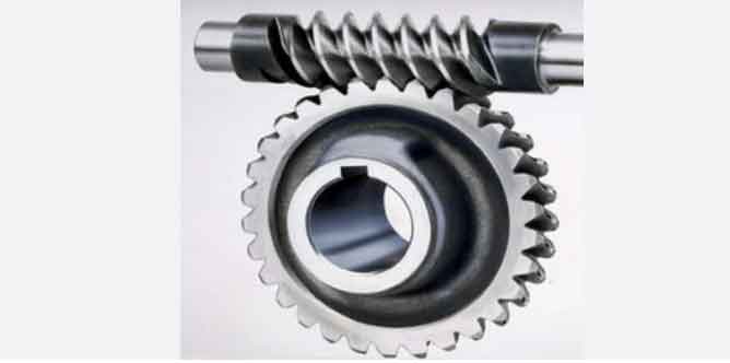
Worm and worm gear combination is generally applied for transmitting motion and power between both crossed axes. Worm gear and worn, which locate upon its mid-plane, are equal to wheel and rack within mechanism of gear – rack. And worm gear is one of the important parts of worm and worm gear.
Worm gears are a type of mechanical power transmission system used to transfer rotational motion between two perpendicular shafts. They belong to the family of gears, which are mechanical devices that transmit power and motion between rotating components.
The key components of a worm gear system are the worm and the worm wheel, also known as the worm gear. The worm resembles a threaded cylinder or screw, while the worm wheel is a toothed wheel. The threads on the worm mesh with the teeth on the worm wheel, and this interaction facilitates the transmission of motion and power.
Here’s a brief overview of the characteristics and applications of worm gears:
- Gear Ratio: Worm gears have a high gear ratio, typically ranging from 5:1 to 300:1. The gear ratio is the number of teeth on the worm wheel divided by the number of threads on the worm. This high gear ratio allows for significant speed reduction or torque increase, making them suitable for applications where high reduction is needed.
- Power Transmission Direction: The power transmission in worm gears is unidirectional, meaning that the worm can drive the worm wheel, but not vice versa. This characteristic provides an inherent self-locking feature, which prevents the driven shaft from back-driving the driving shaft.
- Efficiency: While worm gears offer a high gear ratio, their efficiency can be lower compared to other types of gears due to increased friction between the mating surfaces. Consequently, they are not recommended for applications where high efficiency is critical.
- Applications: Worm gears find applications in various industries, including machinery, automotive, robotics, and industrial equipment. They are commonly used in conveyor systems, lifts, hoists, steering mechanisms, and other applications that require high torque and speed reduction.
- Lubrication: Proper lubrication is crucial for worm gears to reduce friction and wear between the worm and worm wheel. Some worm gears are designed to be self-lubricating, while others require external lubrication.
- Materials: Worm gears are typically made from materials such as steel, bronze, or aluminum, depending on the specific application’s requirements.
- Noise and Vibration: Worm gears can generate more noise and vibration compared to other gear types, which may be a consideration in certain applications.
It is essential to consider the specific requirements of the application, such as load, speed, efficiency, and space constraints when choosing the appropriate gear system. While worm gears offer distinct advantages, they also have certain limitations that need to be carefully evaluated to ensure optimal performance and reliability in the chosen application.
Chapter One: What are Worm Gears?
Worm gears are a type of mechanical gears used for power transmission between non-parallel and perpendicular shafts. They consist of a helical gear called the “worm” that meshes with a toothed wheel known as the “worm gear” or “worm wheel.” The worm gear is driven by the rotation of the worm, allowing the transmission of motion and power at a right angle. This unique design gives worm gears some distinctive features and applications.
Key Features of Worm Gears:
- Speed Reduction: Worm gears can achieve significant speed reduction ratios in a single stage. The number of teeth on the worm compared to the worm gear determines the reduction ratio.
- Self-Locking: One of the most notable characteristics of worm gears is their self-locking capability. When the worm gear is not actively driven, it resists back-driving, preventing the driven shaft from rotating the driving shaft. This feature is beneficial for applications where the load needs to be held in a fixed position.
- Right-Angle Power Transmission: Worm gears are particularly useful for transmitting power between shafts that are at a right angle to each other, making them suitable for applications with space constraints.
- Quiet Operation: Properly designed and lubricated worm gears can operate smoothly and quietly.
- Compact Design: Worm gears have a compact design, making them suitable for various industrial applications where space is limited.
It’s important to note that while worm gears offer unique advantages, they also have limitations, such as relatively lower efficiency due to sliding friction and potential heat generation during operation. Therefore, engineers carefully consider the specific requirements of each application when selecting worm gears to ensure optimal performance and reliability.
For getting a larger gear reduction ratio, it’s time to adopt a worm gear. Generally speaking, the reduction ratio of worm gear is around 20:1, even up to 300:1 or larger.
Chapter Two: How Worm Gears Work?
Worm gears work on the principle of a helical gear (the “worm”) engaging with a toothed wheel (the “worm gear” or “worm wheel”). The worm gear has screw-like teeth that mesh with the helical teeth of the worm. This interaction allows the worm gear to transmit motion and power at a right angle to the axis of the worm.
Key Aspects of How Worm Gears Work:
- Helical Worm: The worm is a cylindrical gear with helical teeth that are cut at an angle to the gear’s axis in a helix pattern. When the worm rotates, the helical teeth mesh with the teeth of the worm gear.
- Right-Angle Power Transmission: Worm gears are primarily used for transmitting motion and power between non-parallel and perpendicular shafts. The worm’s rotation is at a right angle to the axis of the worm gear.
- Reduction Ratio: The number of teeth on the worm compared to the number of teeth on the worm gear determines the reduction ratio of the gear system. Worm gears can achieve significant speed reduction in a single stage.
- Self-Locking: One of the critical features of worm gears is their self-locking capability. When the worm gear is not actively driven, it resists back-driving, preventing the driven shaft from rotating the driving shaft. This self-locking feature is beneficial for applications where the load needs to be held in a fixed position.
- Sliding Friction: During operation, the worm gear and the worm tooth surfaces slide against each other, resulting in sliding friction. This sliding action can lead to heat generation and reduced mechanical efficiency.
- Thrust Load: Worm gears generate an axial thrust force due to the helical angle of the worm. Proper bearing arrangements are required to accommodate this thrust load.
Operation of Worm Gears:
When the worm rotates, its helical teeth mesh with the worm gear’s teeth, causing the worm gear to rotate. The angle of the helix on the worm causes the teeth to engage gradually. As a result, the gear system can achieve a high reduction ratio and smooth motion transmission.
The self-locking feature of worm gears makes them suitable for applications where it is essential to prevent back-driving and hold a load in place, even when the power is not actively applied. However, the sliding action during engagement and the potential for heat generation make worm gears less efficient compared to some other gear types.
Worm gears find applications in various industries, such as elevators, cranes, conveyor systems, and other applications requiring right-angle power transmission and self-locking capabilities. Proper lubrication and design considerations are essential to ensure the efficient and reliable operation of worm gears.
Chapter Three:The Functions and Characteristics of Worm Gears

Many worm gears also have some interesting features other gear groups have not. For instance, a worn can easily rotate a gear but a gear can not rotate a worn. It’s because of too small quoin upon the screw. When a gear tries to rotate a screw, the friction between two parts will make the screw remain in the original position. This function is much playful in transmission systems and other fields. When a motor no longer keeps rotation, the kind locking function can be acted as its brake. Another amusing application in worm gears is differential mechanisms. And the kind mechanisms are mainly applied in some high performance cars and trucks. So worm gears have been important friends in our modern life.
Functions of Worm Gears:
- Power Transmission at Right Angles: The primary function of worm gears is to transmit motion and power between non-parallel and perpendicular shafts. The worm’s rotation is at a right angle to the axis of the worm gear, allowing the gear system to change the direction of motion.
- Speed Reduction: Worm gears are capable of achieving significant speed reduction ratios in a single stage. The reduction ratio is determined by the number of teeth on the worm compared to the number of teeth on the worm gear.
- Self-Locking: One of the unique functions of worm gears is their self-locking capability. When the worm gear is not actively driven, it resists back-driving, preventing the driven shaft from rotating the driving shaft. This feature is useful for applications where the load needs to be held in a fixed position.
- Load Holding: Worm gears are well-suited for applications requiring load holding due to their self-locking nature. This is particularly useful in situations where the gear system needs to maintain a stable position even when the power is not actively applied.
Characteristics of Worm Gears:
- Helical Worm: Worm gears have a helical worm with teeth cut at an angle to the gear’s axis in a helix pattern. This helical tooth design allows for gradual engagement, reducing noise and vibration during gear meshing.
- Sliding Friction: During operation, the worm gear and worm teeth surfaces slide against each other, resulting in sliding friction. This sliding action can lead to heat generation and reduced mechanical efficiency in worm gear systems.
- Efficiency: Worm gears generally have lower efficiency compared to some other gear types due to the sliding friction between the worm and worm gear teeth.
- Axial Thrust: Worm gears generate an axial thrust force due to the helix angle of the worm. Proper bearing arrangements are required to accommodate this thrust load.
- Compact Design: Worm gears have a compact design, making them suitable for applications with limited space, especially when right-angle power transmission is needed.
- Quiet Operation: When properly designed and lubricated, worm gears can operate smoothly and quietly.
The unique characteristics of worm gears, such as self-locking and right-angle power transmission, make them suitable for specific applications where these features are essential. However, engineers also consider the limitations, such as reduced efficiency and sliding friction, when selecting worm gears for particular gear systems. Proper lubrication and design considerations are crucial to ensure the efficient and reliable operation of worm gears in various mechanical applications.
Chapter Four: How Worm Gears are Manufactured
The manufacturing process of worm gears involves several steps, including material selection, gear design, gear cutting, heat treatment, and finishing. Below are the key stages in the manufacturing of worm gears:
- Material Selection: The first step is selecting the appropriate material for both the worm and the worm gear. Common materials used for worm gears include alloy steel, stainless steel, bronze, and cast iron. The choice of material depends on factors such as load capacity, wear resistance, and the application environment.
- Gear Design: The next step is designing the worm gear and worm using computer-aided design (CAD) software. The design includes specifying the gear dimensions, tooth profile, helix angle, number of teeth, and other critical parameters. Engineers also consider factors like the desired reduction ratio and load capacity during the design process.
- Gear Cutting: The gear cutting process is crucial for creating the helical teeth on both the worm and the worm gear. Common methods for gear cutting include hobbing and milling. In hobbing, a hob cutter is used to generate the helical teeth on the worm by rotating the workpiece against the hob. For worm gear cutting, a hob cutter is used to create the helical teeth in the worm gear.
- Heat Treatment: After gear cutting, the worm and worm gear are subjected to heat treatment to enhance their hardness and strength. Processes like carburizing, quenching, and tempering are used to achieve the desired material properties.
- Finishing Operations: Following heat treatment, the worm gear and worm undergo finishing operations to ensure precise dimensions and smooth tooth surfaces. Finishing processes may include grinding, lapping, and honing.
- Assembly: Once the worm and worm gear are manufactured and finished, they are assembled together in the gear system. Proper alignment is critical to ensure efficient and reliable operation.
- Lubrication: Worm gears require appropriate lubrication to reduce friction and wear during operation. Lubricants with good adhesion and film strength are chosen to ensure smooth gear meshing and extend the gear’s lifespan.
- Quality Control: Throughout the manufacturing process, quality control measures are implemented to inspect the gear dimensions, tooth profiles, surface finish, and other critical features. This ensures that the worm gears meet the specified design requirements and performance standards.
Manufacturing worm gears requires precision and expertise to achieve the desired gear characteristics, efficiency, and reliability. Proper gear design, gear cutting, heat treatment, and finishing are essential to ensure the worm gears perform optimally in their intended applications.
Chapter Five: Types of Worm Gears
Worm gears can be classified into various types based on their design, configuration, and application. Here are the main types of worm gears:
- Single-Start Worm Gear: In a single-start worm gear, the worm has a single thread, and the worm gear has one set of teeth. This type of worm gear is commonly used in applications requiring moderate speed reduction.
- Multi-Start Worm Gear: Multi-start worm gears have worms with multiple threads, and the worm gear also has a corresponding number of sets of teeth. Multi-start worm gears offer higher gear ratios and can handle higher loads compared to single-start worm gears.
- Double Enveloping Worm Gear: In double-enveloping worm gears, both the worm and the worm gear tooth profiles wrap around each other. This design provides higher contact ratios, resulting in smoother operation and increased load-carrying capacity.
- Single Enveloping Worm Gear: In single-enveloping worm gears, the worm gear tooth profile wraps around only a portion of the worm. This design is simpler than the double enveloping type and is suitable for various applications.
- Non-Throated Worm Gear: In non-throated worm gears, the worm does not have a throat diameter (no groove around the worm shaft). Non-throated worm gears are suitable for light-duty applications.
- Throated Worm Gear: Throated worm gears have a groove or a throat around the worm shaft. This design allows for better lubrication and reduces friction, resulting in higher efficiency and load-carrying capacity compared to non-throated worm gears.
- Right-Hand and Left-Hand Worm Gears: Worm gears can be classified as right-hand or left-hand based on the direction of their helix. Right-hand worm gears have a clockwise helix, while left-hand worm gears have a counterclockwise helix.
- Co-Axial and Non-Co-Axial Worm Gears: Co-axial worm gears have the worm and worm gear mounted on the same axis, while non-co-axial worm gears have the worm and worm gear mounted on parallel, non-intersecting axes.
- Self-Locking Worm Gear: Worm gears are inherently self-locking, meaning they can hold the load in place without the need for additional braking mechanisms. This feature is beneficial for applications requiring load holding and safety.
Each type of worm gear offers specific advantages and is suitable for different applications based on load requirements, speed reduction ratios, efficiency considerations, and the need for self-locking characteristics. The selection of the right type of worm gear depends on the specific needs of the gear system and the intended application.
Chapter Six: The Advantages and Disadvantages of Worm Gears
Worm gears offer several advantages and disadvantages compared to other types of gears. Here are some of the key advantages and disadvantages of worm gears:
Advantages:
- High Reduction Ratios: Worm gears can achieve high speed reduction ratios in a single stage, making them suitable for applications requiring significant speed reduction.
- Right-Angle Power Transmission: Worm gears are designed to transmit motion and power at a right angle to the axis of the worm, making them ideal for applications where the driving and driven shafts are perpendicular to each other.
- Self-Locking: Worm gears have a self-locking feature, meaning they can hold the load in place without the need for additional braking mechanisms. This characteristic is beneficial for applications requiring load holding and safety, such as elevators and hoists.
- Compact Design: Worm gears have a compact design, making them suitable for applications with limited space.
- Quiet Operation: When properly designed and lubricated, worm gears can operate smoothly and quietly.
- Versatility: Worm gears can be designed with various configurations and types to suit different applications and load capacities.
Disadvantages:
- Reduced Efficiency: Worm gears generally have lower efficiency compared to some other gear types due to the sliding friction between the worm and worm gear teeth. This can result in heat generation and energy loss.
- Limited Load Capacity: Worm gears are generally not suitable for high-load applications due to the sliding contact between the teeth, which can cause wear and reduced gear life.
- Backlash: Worm gears can have higher levels of backlash compared to other gear types, which can affect positioning accuracy in some applications.
- Heat Generation: The sliding action during gear engagement can result in heat generation, which may require additional cooling or lubrication measures.
- Complex Manufacturing: Manufacturing worm gears can be more complex and expensive compared to other types of gears due to their helical tooth profile and unique design.
- Limited Speeds: Worm gears have limitations on their operating speeds due to their sliding contact and potential for overheating at high speeds.
Despite their disadvantages, worm gears are still widely used in various applications, especially when right-angle power transmission, load holding, and self-locking capabilities are required. Engineers must carefully consider the advantages and disadvantages of worm gears when selecting the appropriate gear type for specific applications.
Chapter Sevent: The Applications of Worm Gears
Worm gears are used in a wide range of applications across various industries due to their unique characteristics and advantages. Some of the common applications of worm gears include:
- Elevators and Lifts: Worm gears are widely used in elevator and lift systems due to their self-locking feature, which ensures that the elevator remains in a fixed position even when power is not applied.
- Hoists and Cranes: Worm gears provide smooth and controlled lifting and lowering motions in hoists and cranes, making them suitable for heavy lifting applications.
- Conveyor Systems: Worm gears are used in conveyor systems to control the movement of materials and products along the conveyor belts.
- Automotive Industry: Worm gears are used in automotive applications, such as automotive steering systems and power windows, where right-angle power transmission and self-locking characteristics are required.
- Valve Actuators: Worm gears are used in valve actuators to control the flow of fluids in pipelines and other industrial systems.
- Winches and Windlasses: Worm gears are employed in winches and windlasses to provide controlled and powerful pulling and lifting actions.
- Printing Industry: Worm gears are used in printing machines to control the paper feed and other mechanical movements.
- Robotics: Worm gears are utilized in robotic systems to control the movement and positioning of robot arms and other robotic components.
- Packaging Machinery: Worm gears are used in packaging machinery to control the movement and positioning of packaging materials.
- Textile Industry: Worm gears are used in textile machinery for various functions, such as controlling yarn tension and thread guidance.
- Machine Tools: Worm gears are used in machine tools for precise positioning and control of tool movements.
- Stage and Theater Equipment: Worm gears are employed in stage and theater equipment to control the movement of curtains, set pieces, and lighting fixtures.
- Food Processing Machinery: Worm gears are used in food processing equipment to control the movement of conveyors and other mechanical components.
- Medical Equipment: Worm gears are used in medical equipment for applications such as controlling the movement of surgical instruments and imaging devices.
- Renewable Energy Systems: Worm gears are used in renewable energy systems, such as solar tracking systems and wind turbine yaw drives.
These are just a few examples of the many applications of worm gears. Worm gears find extensive use in situations where right-angle power transmission, self-locking capability, and controlled motion are essential requirements.