
I conducted a study on measuring the geometric parameters of helical gears using machine vision. The helical gear, due to its helix angle, often introduces shadow artifacts in the end-face image during acquisition. This shadow region degrades the accuracy of parameter extraction. To address this issue, I proposed an improved measurement scheme employing a high-resolution dual-telecentric lens and a close-range backlight source. Combined with the Otsu image binarization method, I obtained a high-quality end-face image of the helical gear. Furthermore, I developed a contour feature point method to extract key points: the intersection of the line connecting the gear center and the centroid of each tooth with the addendum contour, and the intersection of the same line rotated by a certain angle with the dedendum contour. These points were then fitted to circles to measure the addendum and dedendum diameters. Experimental results demonstrate that the absolute measurement error is within 0.02 mm, confirming the effectiveness of the proposed approach.
Introduction
Helical gears are widely used in mechanical transmission systems due to their smooth engagement and high load capacity. Accurate measurement of their geometric parameters, such as the addendum circle diameter, dedendum circle diameter, and tooth count, is critical for quality control. Machine vision provides a non-contact, fast, and reliable solution. However, unlike spur gears, the helical gear’s helix angle causes the side profile to be partially captured in the end-face image, creating a brightness gradient that resembles shadows. This shadow complicates binarization and edge detection. Existing methods, such as Gamma transformation or global low-light enhancement, often lead to information loss or incomplete contours.
In my work, I focused on the helical gear measurement problem. I designed a vision system with a dual-telecentric lens to minimize distortion and a close-range backlight to reduce shadow effects. I adopted Otsu’s thresholding to segment the helical gear region from the background. For parameter extraction, I introduced a contour feature point method that relies on geometric relationships between the gear center, tooth centroids, and the contour. This method is robust to local contour irregularities. I validated the method on a standard helical gear sample and compared it with a conventional minimum circumscribed circle approach.
Measurement System Design
Hardware Setup
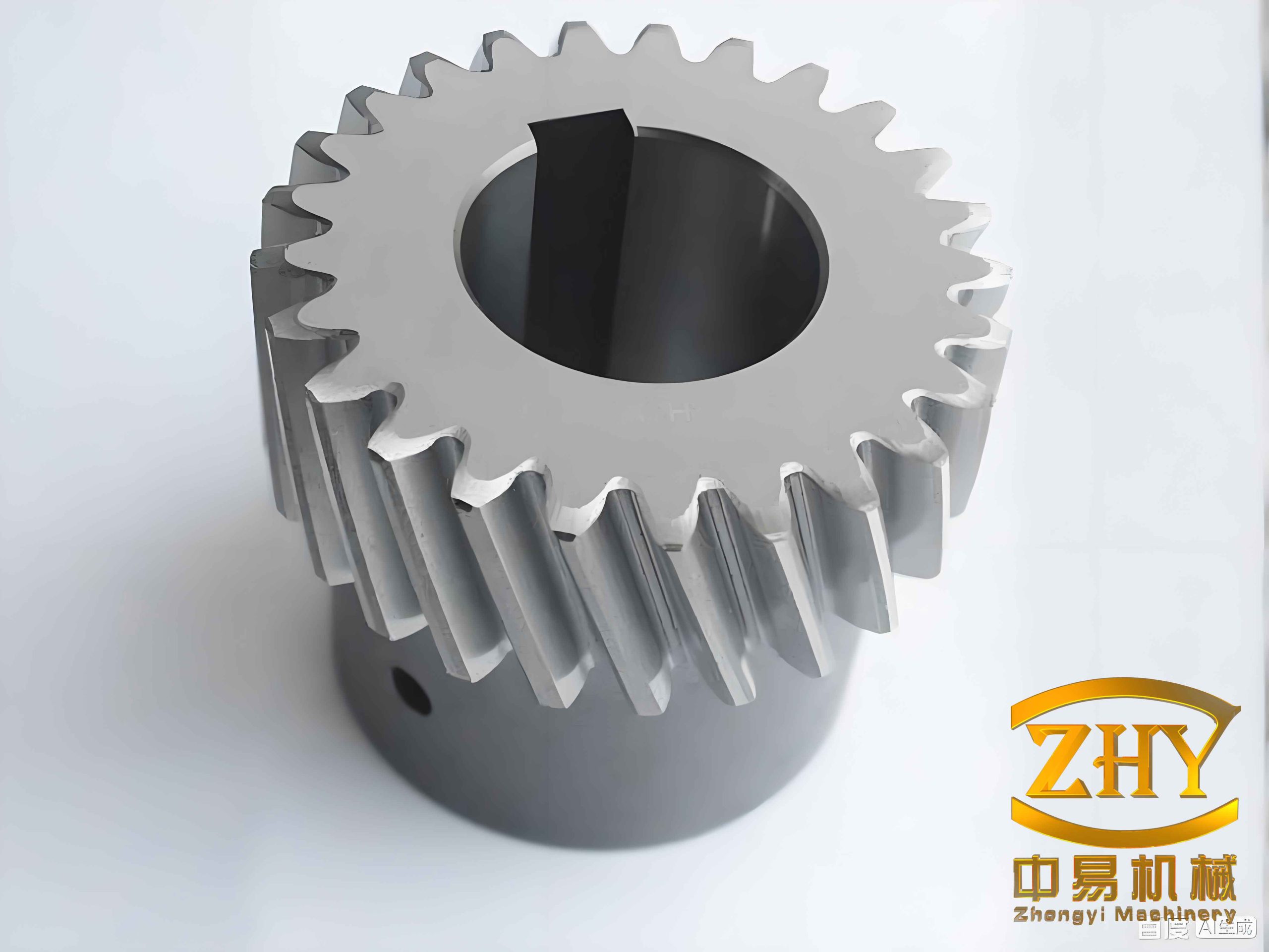
The measurement object was a helical cylindrical gear with parameters: module 2 mm, teeth number Z=18, helix angle β=15°. The target parameters were the addendum circle diameter, dedendum circle diameter, and tooth number. The required measurement accuracy was set to 0.02 mm. The system consisted of:
| Component | Specification |
|---|---|
| Camera | Industrial area-scan camera, 4024×3036 resolution |
| Lens | Dual-telecentric lens, low distortion, large field of view |
| Light source | LED white backlight, close-range illumination |
I compared far-range and close-range backlighting. The close-range setup significantly reduced shadow artifacts, making the helical gear end-face clearer.
System Workflow
The measurement system comprised three modules: exposure optimization, image processing, and parameter measurement.
- Exposure Optimization Module: I preset an initial exposure time T0 and a step Δt. The system automatically adjusted exposure, captured images, and evaluated the exposure status to determine the optimal range. The selected range for this helical gear was 26,000 to 32,000 ms.
- Image Processing Module: Grayscale conversion, bilateral filtering, Otsu binarization, and sub-pixel edge detection were applied.
- Parameter Measurement Module: Using the contour feature point method, I extracted addendum and dedendum diameters and the tooth count.
Image Processing for Helical Gear
Grayscale Conversion
The captured color image was converted to grayscale using the weighted average method:
$$Gray(i,j) = 0.299 \times R(i,j) + 0.587 \times G(i,j) + 0.114 \times B(i,j)$$
where R, G, B are the intensity values at pixel (i,j).
Bilateral Filtering
To reduce noise while preserving edges, I applied bilateral filtering. The output pixel value h(i,j) is given by:
$$h(i,j) = \frac{\sum_{k,l} f(k,l) w_s(k,l) w_r(k,l)}{\sum_{k,l} w_s(k,l) w_r(k,l)}$$
where ws and wr are spatial and intensity weighting functions:
$$w_s(k,l) = \exp\left(-\frac{(i-k)^2 + (j-l)^2}{2\sigma_s^2}\right)$$
$$w_r(k,l) = \exp\left(-\frac{|f(i,j)-f(k,l)|^2}{2\sigma_r^2}\right)$$
Otsu Binarization
Otsu’s method automatically selects a threshold T that maximizes the between-class variance. The algorithm calculates the optimal T that separates the helical gear region (foreground) from the background. After binarization, small connected components were removed using a shape operator, retaining only the main helical gear area.
Sub-Pixel Edge Detection
I used the edges_sub_pix operator to extract the gear contour with sub-pixel accuracy. The outer contour was selected using shape constraints.
Exposure Time Optimization
I conducted experiments to find the exposure range that minimizes measurement error for the helical gear. With a fixed light intensity level of 30, I varied exposure time from 24,000 ms to 42,000 ms in steps of 1,000 ms. The absolute errors for addendum and dedendum diameters were recorded. Table 2 summarizes the results for the optimal range.
| Exposure time (ms) | Addendum diameter error (mm) | Dedendum diameter error (mm) |
|---|---|---|
| 26,000 | 0.019 | 0.018 |
| 28,000 | 0.017 | 0.016 |
| 30,000 | 0.018 | 0.017 |
| 32,000 | 0.020 | 0.019 |
The optimal exposure interval was 26,000–32,000 ms, where errors remained below 0.02 mm.
Measurement Method: Contour Feature Points
Tooth Count Determination
First, I computed the minimum circumscribed circle and maximum inscribed circle of the helical gear contour. Their average diameter was used to create a circular mask. The difference between the mask and the binarized image yielded the tooth region. The number of connected components in that region gave the tooth count Z.
Gear Center Extraction
I used a caliper tool (50 pixel length, 1 pixel width, 180 tools) to measure points on the bore circle. A least-squares circle fit provided the center coordinates (xc, yc).
Addendum Circle Fitting
For each tooth connected component, I calculated its centroid (xi, yi). I drew a line from the gear center to each centroid and extended it to intersect the outer contour. To reduce noise, I also considered lines 1° left and right of the original line, and averaged the intersection points. All intersection points were fitted to a circle using the least-squares method.
The least-squares circle fitting minimizes the sum of squared distances from the points to the fitted circle. The objective function is:
$$\sum_{j=1}^{N} \left( (x_j – x_0)^2 + (y_j – y_0)^2 – R^2 \right)^2$$
where (x0, y0) is the center and R is the radius.
Dedendum Circle Fitting
I rotated each line from the center to the tooth centroid by an angle θ = π/(2Z) in the clockwise direction. The rotated lines intersected the inner (dedendum) contour. The intersection points were collected and fitted to a circle using the same least-squares method. Figure 1 (inserted via hyperlink) illustrates the fitting result.
Experimental Results and Comparison
I measured a helical gear with theoretical addendum diameter 44.19 mm and dedendum diameter 35.19 mm. Table 3 compares the proposed method with the conventional method from the literature (using minimum enclosing circles).
| Parameter | Theoretical value | Literature method [12] | Absolute error (Lit.) | Proposed method | Absolute error (Prop.) |
|---|---|---|---|---|---|
| Addendum diameter | 44.19 | 44.3077 | 0.1177 | 44.1716 | 0.0184 |
| Dedendum diameter | 35.19 | 35.0860 | 0.1040 | 35.2076 | 0.0176 |
The conventional method overestimates the addendum and underestimates the dedendum due to sensitivity to protruding points. My contour feature point method achieved errors within 0.02 mm. To further validate generalizability, I also measured a spur gear (module 2, Z=18, addendum diameter 40 mm, dedendum diameter 31 mm). Results are shown in Table 4.
| Parameter | Theoretical value | Literature method [12] | Absolute error (Lit.) | Proposed method | Absolute error (Prop.) |
|---|---|---|---|---|---|
| Addendum diameter | 40.00 | 40.0904 | 0.0904 | 40.0159 | 0.0159 |
| Dedendum diameter | 31.00 | 30.9025 | 0.0975 | 30.9846 | 0.0154 |
The proposed method consistently maintained absolute errors below 0.02 mm for both helical and spur gears.
Conclusion
I addressed the shadow problem in helical gear end-face image acquisition by using a close-range backlight and Otsu binarization. The contour feature point method effectively extracts addendum and dedendum diameters by leveraging geometric relationships between gear center, tooth centroids, and contour intersections. Experimental results showed that the absolute measurement error for helical gear parameters is within 0.02 mm, satisfying the accuracy requirement. The method is also applicable to spur gears, demonstrating its versatility. Future work may extend this approach to measure other helical gear parameters such as helix angle and tooth thickness.