
I have developed and put into production a three-roll skew rolling process for gear hob blanks. The purpose is to replace the conventional route in which a forged gear blank is machined extensively before heat treatment and final grinding. In my method, a heated bar or a compact forged gear blank is fed between three synchronized rolls. The rolls form the helical tooth profile close to the final shape, so the subsequent machining allowance is small and the material waste associated with a forged gear blank is greatly reduced. I use a semi-automatic arrangement, and the tooling is designed so that the rolled gear hob blank has a stable pitch, a sound metal flow line, and a fine carbide distribution after heat treatment.
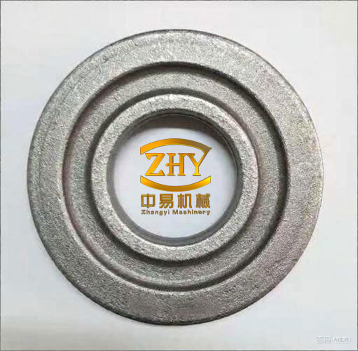
In my experience, the advantages of hot skew rolling over the traditional forged gear blank route are not limited to material saving. The process also improves the working environment, reduces impact load on the hammer, lowers noise, and gives a more favorable grain flow. Because the teeth are formed by plastic flow rather than by cutting a forged gear blank, the flow lines follow the tooth contour instead of being interrupted at the root and flank. This is particularly important for gear hobs, where the relief grinding operation can otherwise expose defects originating in a forged gear blank.
| Item | Conventional forged gear blank route | Hot three-roll skew rolling route | Effect in my design |
|---|---|---|---|
| Material utilization | Low to medium | High | Less waste from the forged gear blank |
| Production level | Manual or semi-manual forging | Semi-automatic rolling | Higher output and steadier quality |
| Impact load | High during forging | Low during rolling | Less vibration and lower noise |
| Metal flow | May cut across flow lines | Follows tooth contour | Better tooth root and flank strength |
| Center defects | Possible in a forged gear blank | Usually avoided | Fewer scrap parts after tooth relief |
| Hardness uniformity | Depends on forging practice | More uniform after controlled cooling | Better red hardness and toughness |
| Allowance | Large | Small | Less machining and shorter cycle |
I begin the roll design by fixing the rolled gear hob blank geometry. The blank is essentially a cylindrical body with a helical tooth profile. The main parameters are the outside diameter, the root diameter, the mean diameter, the tooth height, the top width, the normal pressure angle, the helix angle, and the axial pitch. For the forged gear blank replacement strategy, I always compare these values with the corresponding forged gear blank drawing, because the rolled blank must leave enough material for finishing but not so much that the rolling load becomes excessive.
| Parameter | Symbol | Typical value in my work |
|---|---|---|
| Rolled blank outside diameter | \(d_{b,o}\) | 70–90 mm |
| Rolled blank root diameter | \(d_{b,i}\) | 55–75 mm |
| Rolled blank mean diameter | \(d_{b,m}\) | 62–82 mm |
| Tooth height | \(h_b\) | 8–12 mm |
| Normal pressure angle | \(\alpha_n\) | 20° |
| Helix angle of the blank | \(\beta_w\) | 3°–8° |
| Axial pitch | \(t_b\) | 10–15 mm |
The first major choice is the roll type. I selected a single-start left-hand roll. Its spiral angle is smaller than the spiral angle of the rolled gear hob blank. The mounting angle is the difference between the two spiral angles. This arrangement is simple to manufacture and easy to keep in alignment. The pitch of the rolled gear hob blank remains stable within the tolerance band, and the tooling is convenient to store and maintain. The main disadvantage is that the pitch is special, so the lathe and grinder must be able to cut and dress the special thread form. Even so, for a forged gear blank replacement line, this is a favorable compromise.
| Roll type | Start | Hand | Spiral angle relation | Mounting angle | My assessment |
|---|---|---|---|---|---|
| Single-start left-hand | 1 | Left | \(\beta_r < \beta_w\) | \(\gamma=\beta_w-\beta_r\) | Simple, stable, and preferred |
| Multi-start | 2 or more | Either | Higher lead | Larger angle | More complex and less stable |
| Right-hand | 1 | Right | Opposite hand | Sum of angles | Not used in my line |
I determine the roll outside diameter and root diameter together. If the roll diameter is too small, the contact between the roll and the hot metal is favorable and the rolling force is lower, but the roll stiffness and strength are insufficient. If the roll diameter is too large, the stiffness is good, but the rolling mill structure becomes bulky and the sliding velocity increases. In my design, I use a ratio of roll diameter to initial billet diameter between 3.0 and 3.5. This range gives a good balance between strength, contact conditions, and stable rolling of the forged gear blank replacement.
$$ \frac{D_{r,o}}{d_{b,0}} = 3.0 \sim 3.5 $$
I prefer to use the root diameter of the roll as the reference and then determine the outside diameter. The reason is that during rolling the center of mass of the blank moves away from the finishing tooth. Under gravity, the blank tends to nod or swing. The farther the center of mass is from the finishing tooth, the stronger the nodding motion becomes. This can cause pitch error, sometimes larger than the allowed value. To prevent this, I add guide wheels behind the rolls. If I use the outside diameter as the reference, the number of guide wheels increases and their manufacture and storage become inconvenient. Therefore I base the design on the root diameter and then calculate the outside diameter.
$$ h_r = h_b + \Delta_c $$
$$ D_{r,o} = D_{r,i} + 2 h_r $$
$$ D_{r,m} = D_{r,o} – h_r = D_{r,i} + h_r $$
Here \(h_r\) is the roll tooth height, \(h_b\) is the rolled gear hob blank tooth height, and \(\Delta_c\) is the clearance between the blank crest and the roll root. I usually take \(\Delta_c=0.2\) to \(0.5\) mm. The guide wheel outside diameter is set from the blank outside diameter and a small control clearance.
$$ D_{g,o} = d_{b,o} + 2 \Delta_g $$
| Roll diameter parameter | Symbol | Equation | Example value |
|---|---|---|---|
| Roll root diameter | \(D_{r,i}\) | Reference | 179.0 mm |
| Roll tooth height | \(h_r\) | \(h_b+\Delta_c\) | 10.5 mm |
| Roll outside diameter | \(D_{r,o}\) | \(D_{r,i}+2h_r\) | 200.0 mm |
| Roll mean diameter | \(D_{r,m}\) | \(D_{r,o}-h_r\) | 189.5 mm |
| Guide wheel outside diameter | \(D_{g,o}\) | \(d_{b,o}+2\Delta_g\) | 81.0 mm |
The roll length is divided into a conical forming section and a cylindrical finishing section. The forming section performs most of the reduction. The finishing section calibrates the pitch and flank. I calculate the total radial compression first, then the reduction per workpiece revolution, then the number of forming revolutions. The forming length follows from the number of forming revolutions and the axial pitch.
$$ \Delta = d_{b,0} – d_{b,i} $$
$$ n_f = \frac{\Delta}{\delta} $$
$$ L_f = n_f t_b + L_c $$
In these equations, \(\Delta\) is the total radial compression, \(\delta\) is the radial reduction per workpiece revolution for one roll, \(n_f\) is the number of forming revolutions, \(t_b\) is the axial pitch of the rolled gear hob blank, and \(L_c\) is a clearance allowance. The clearance allowance accounts for backlash in the rolling mill and for the elastic deformation of the roll stand. I usually introduce a clearance coefficient \(k_c\), so the forming length becomes
$$ L_f = k_c \frac{\Delta}{\delta} t_b $$
The cylindrical finishing section must not be too long. If it is too long, the rolling force rises unnecessarily and the roll teeth may interfere with the already formed profile, damaging the flank surface of the rolled gear hob blank. If it is too short, the profile is not fully calibrated. From my trials, the finishing section should keep the blank in contact with the finishing teeth for at least two to three revolutions.
$$ L_s = n_s t_b, \quad n_s = 2 \sim 3 $$
$$ L_r = L_f + L_s + L_e $$
Here \(L_s\) is the finishing length, \(n_s\) is the number of finishing revolutions, and \(L_e\) is an end allowance for the roll shoulders and run-out. The cone angle of the forming section is selected so that the blank is bitten smoothly and the reduction is progressive.
$$ \phi = \arctan\left(\frac{\Delta}{L_f}\right) $$
| Length item | Symbol | Equation | Example value |
|---|---|---|---|
| Total radial compression | \(\Delta\) | \(d_{b,0}-d_{b,i}\) | 6.0 mm |
| Reduction per revolution | \(\delta\) | Selected from trials | 0.6 mm |
| Number of forming revolutions | \(n_f\) | \(\Delta/\delta\) | 10 |
| Forming length | \(L_f\) | \(n_f t_b+L_c\) | 75.4 mm |
| Finishing revolutions | \(n_s\) | Selected | 2.5 |
| Finishing length | \(L_s\) | \(n_s t_b\) | 31.4 mm |
| Total roll length | \(L_r\) | \(L_f+L_s+L_e\) | 120.0 mm |
| Forming cone angle | \(\phi\) | \(\arctan(\Delta/L_f)\) | 4.55° |
The forming pass design is the heart of the roll. I do not use a simple uniform press-in schedule. Instead, I use a mixed press-in method. The first few teeth before the finishing tooth are arranged as a layered press-in section, while the remaining teeth are arranged as a closed press-in section. This gives the forming teeth approximately equal strength and stiffness. After the pass is cut, I correct the tooth flanks as required. The mixed press-in method avoids excessive load on the first teeth and reduces the risk of overfilling the gap.
| Pass zone | Function | Tooth type | Load character |
|---|---|---|---|
| Entry cone | Bite and initial reduction | Layered press-in | Gradual |
| Middle cone | Main forming | Closed press-in | High but balanced |
| Pre-finishing | Profile correction | Layered correction | Moderate |
| Finishing cylinder | Calibration | Full profile | Uniform |
For the flank correction, I define the fixed measuring chord tooth thickness of the finishing tooth. The correction amount on the forming teeth is then calculated from this value. The front pitch and back pitch of the corrected teeth are adjusted so that the metal flows smoothly into the finishing pass. The tooth height is reduced in steps from the finishing tooth back toward the entry.
$$ s_i = s_f \pm \Delta s $$
$$ t_{\text{front}} = t + \Delta s $$
$$ t_{\text{back}} = t – \Delta s $$
$$ h_i = h_f – i \Delta h $$
In these equations, \(s_f\) is the fixed measuring chord tooth thickness of the finishing tooth, \(\Delta s\) is the flank correction amount, \(t\) is the nominal axial pitch, \(t_{\text{front}}\) and \(t_{\text{back}}\) are the corrected pitches on the front and back sides of the press-in teeth, \(h_f\) is the finishing tooth height, and \(\Delta h\) is the height reduction per forming step. I keep the correction amount small enough to avoid a sharp step in the pass, but large enough to prevent the roll from rubbing the already formed flank of the forged gear blank replacement.
| Tooth number from finishing | Zone | Flank correction \(\Delta s\) | Front pitch | Back pitch | Height reduction |
|---|---|---|---|---|---|
| 0 | Finishing | 0.00 mm | 12.566 mm | 12.566 mm | 0.00 mm |
| 1 | Pre-finishing | 0.10 mm | 12.666 mm | 12.466 mm | 0.15 mm |
| 2 | Pre-finishing | 0.20 mm | 12.766 mm | 12.366 mm | 0.30 mm |
| 3 | Forming | 0.30 mm | 12.866 mm | 12.266 mm | 0.45 mm |
| 4 | Forming | 0.40 mm | 12.966 mm | 12.166 mm | 0.60 mm |
| 5 | Entry | 0.50 mm | 13.066 mm | 12.066 mm | 0.75 mm |
I also select the stagger method carefully. The three rolls have the same pitch and the same axial position. Their spiral pass starting points are separated by 120° around the rolled gear hob blank. This is the circumferential stagger method. I prefer it because the three rolls have identical conical angles and identical axial positions. During rolling, each roll imposes the same radial reduction for a given workpiece rotation. The rolling action is therefore balanced and smooth. No special stagger shims are required, which reduces manufacturing cost and makes the tooling easier to use.
$$ \theta_i = 120^\circ (i-1), \quad i=1,2,3 $$
$$ \Delta r_1 = \Delta r_2 = \Delta r_3 = \frac{\Delta}{3} $$
The disadvantage of circumferential stagger is that initial biting can be more difficult because the three pass starts are not aligned in the same axial plane. I overcome this by increasing the forming length slightly and by reducing the thickness of the first press-in teeth. This allows the heated billet to enter smoothly and prevents the rolls from slipping on the surface of the forged gear blank replacement.
| Stagger method | Axial position | Spiral start relation | Radial reduction | Manufacturing | My choice |
|---|---|---|---|---|---|
| Axial stagger | Different | Aligned | Not equal at all times | Shims required | Not preferred |
| Circumferential stagger | Same | 120° apart | Equal | No shims | Preferred |
The blank calculation must be accurate because the volume of the rolled gear hob blank determines the initial billet diameter. I treat the rolled blank as a combination of a cylindrical root body and a helical tooth body. For one axial pitch, the root cylinder volume is
$$ V_c = \pi r_i^2 t_b $$
where \(r_i\) is the root radius and \(t_b\) is the axial pitch. The helical tooth volume can be calculated by the Pappus theorem. If \(A_h\) is the cross-sectional area of the tooth in the axial plane and \(r_c\) is the centroid radius of that area, then the volume of one helical turn is
$$ V_h = A_h \sqrt{(2\pi r_c)^2 + t_b^2} $$
For a trapezoidal tooth section, the area is
$$ A_h = \frac{s_a + s_b}{2} h_b $$
where \(s_a\) is the top width, \(s_b\) is the root width, and \(h_b\) is the tooth height. The total rolled volume per pitch is therefore
$$ V_{\text{rolled}} = V_c + V_h $$
$$ V_{\text{rolled}} = \pi r_i^2 t_b + \frac{s_a + s_b}{2} h_b \sqrt{(2\pi r_c)^2 + t_b^2} $$
If I use a more rigorous cylindrical coordinate integration, I write the helical tooth volume as
$$ V_h = \int_0^{2\pi} \int_{r_i}^{r_o(\theta)} \rho \, \frac{t_b}{2\pi} \, d\rho \, d\theta $$
where \(r_o(\theta)\) is the outer radius of the tooth as a function of angular position. In practice, the Pappus form is accurate enough for the forged gear blank replacement design, and it is easier to evaluate in the workshop.
| Volume component | Symbol | Equation | Example value |
|---|---|---|---|
| Root cylinder | \(V_c\) | \(\pi r_i^2 t_b\) | 35,343 mm³ |
| Tooth area | \(A_h\) | \((s_a+s_b)h_b/2\) | 80 mm² |
| Centroid radius | \(r_c\) | Measured from design | 34.5 mm |
| Helical tooth volume | \(V_h\) | \(A_h\sqrt{(2\pi r_c)^2+t_b^2}\) | 17,352 mm³ |
| Rolled blank volume per pitch | \(V_{\text{rolled}}\) | \(V_c+V_h\) | 52,695 mm³ |
I then equate the rolled volume to the billet volume. The billet is a cylinder of diameter \(d_0\) and length \(L_0\). If the axial length changes very little, which is typical in hot skew rolling of a gear hob blank, I can use one pitch as the control volume. The billet volume per pitch is
$$ V_{\text{billet}} = \frac{\pi}{4} d_0^2 t_b $$
Allowing for scale loss and flash, I introduce a loss factor \(\eta\). The required billet diameter is
$$ d_0 = \sqrt{\frac{4 V_{\text{rolled}}}{\pi t_b (1-\eta)}} $$
For a forged gear blank replacement, I also add a machining allowance \(\delta_s\) to the billet diameter. The cut billet diameter is
$$ d_{\text{cut}} = d_0 + \delta_s $$
I usually take \(\delta_s=1.0\) to \(1.5\) mm for small and medium gear hob blanks, and slightly larger for large sizes. The calculated diameter is checked against the roll opening and the guide wheel setting before the first trial.
| Billet calculation item | Symbol | Equation | Example value |
|---|---|---|---|
| Rolled volume per pitch | \(V_{\text{rolled}}\) | Calculated above | 52,695 mm³ |
| Axial pitch | \(t_b\) | From blank drawing | 12.566 mm |
| Loss factor | \(\eta\) | Scale and flash | 0.04 |
| Theoretical billet diameter | \(d_0\) | \(\sqrt{4V_{\text{rolled}}/(\pi t_b(1-\eta))}\) | 65.4 mm |
| Machining allowance | \(\delta_s\) | Selected | 0.6 mm |
| Cut billet diameter | \(d_{\text{cut}}\) | \(d_0+\delta_s\) | 66.0 mm |
I now give a complete design example. The target is a gear hob blank with an outside diameter of 80 mm, a mean diameter of 70 mm, a root diameter of 60 mm, a tooth height of 10 mm, a top width of 6 mm, a normal pressure angle of 20°, and a helix angle of 5°. The axial pitch is 12.566 mm. The initial billet is a cut bar from a forged gear blank replacement stock. The total radial compression is 6 mm. The reduction per workpiece revolution for one roll is 0.6 mm, so the number of forming revolutions is 10. The forming length is 75.4 mm, the finishing length is 31.4 mm, and the total roll length is 120 mm.
| Design parameter | Symbol | Value |
|---|---|---|
| Rolled blank outside diameter | \(d_{b,o}\) | 80.0 mm |
| Rolled blank mean diameter | \(d_{b,m}\) | 70.0 mm |
| Rolled blank root diameter | \(d_{b,i}\) | 60.0 mm |
| Blank tooth height | \(h_b\) | 10.0 mm |
| Blank top width | \(s_a\) | 6.0 mm |
| Normal pressure angle | \(\alpha_n\) | 20° |
| Blank helix angle | \(\beta_w\) | 5° |
| Axial pitch | \(t_b\) | 12.566 mm |
| Initial billet diameter | \(d_0\) | 66.0 mm |
| Total radial compression | \(\Delta\) | 6.0 mm |
| Reduction per revolution | \(\delta\) | 0.6 mm |
| Forming revolutions | \(n_f\) | 10 |
| Finishing revolutions | \(n_s\) | 2.5 |
For the roll itself, I use a single-start left-hand design. The roll root diameter is 179 mm, the roll tooth height is 10.5 mm, the roll outside diameter is 200 mm, and the roll mean diameter is 189.5 mm. The roll axial pitch is the same as the blank axial pitch, 12.566 mm. The roll helix angle is calculated from the roll mean diameter and the axial pitch.
$$ \tan \beta_r = \frac{t_b}{\pi D_{r,m}} $$
$$ \beta_r = \arctan\left(\frac{t_b}{\pi D_{r,m}}\right) $$
With \(t_b=12.566\) mm and \(D_{r,m}=189.5\) mm, I obtain \(\beta_r \approx 1.21^\circ\). The blank helix angle is \(\beta_w=5^\circ\). The roll mounting angle is therefore
$$ \gamma = \beta_w – \beta_r \approx 3.79^\circ $$
I set the roll mounting angle on the mill to this value and verify it with a dial indicator before heating the first forged gear blank replacement. The guide wheels are set to control the outside diameter of the rolled gear hob blank. Their outside diameter is 81 mm with a small clearance.
| Roll parameter | Symbol | Value |
|---|---|---|
| Roll type | Single-start left-hand | — |
| Roll root diameter | \(D_{r,i}\) | 179.0 mm |
| Roll outside diameter | \(D_{r,o}\) | 200.0 mm |
| Roll mean diameter | \(D_{r,m}\) | 189.5 mm |
| Roll tooth height | \(h_r\) | 10.5 mm |
| Roll axial pitch | \(t_r\) | 12.566 mm |
| Roll helix angle | \(\beta_r\) | 1.21° |
| Blank helix angle | \(\beta_w\) | 5.00° |
| Mounting angle | \(\gamma\) | 3.79° |
| Forming length | \(L_f\) | 75.4 mm |
| Finishing length | \(L_s\) | 31.4 mm |
| Total roll length | \(L_r\) | 120.0 mm |
The technical conditions for the roll are strict. I require the roll material to be a suitable hot-work die steel. After rough machining, the roll is heat treated, then finish machined, and finally surface treated or carburized according to the service temperature. The hardness must be high enough to resist wear but not so high that the roll teeth chip under thermal shock. I inspect the spiral start positions, the pitch error, the cumulative pitch error, the run-out, and the profile after final grinding.
| Technical item | Requirement in my design |
|---|---|
| Roll material | Hot-work die steel or equivalent |
| Hardness after heat treatment | 45–52 HRC at the working zone |
| Surface treatment | Nitriding or carburizing as required |
| Spiral start positions | 120° apart, referenced to the keyway |
| Outside diameter consistency | ±0.02 mm within a set |
| Mean diameter consistency | ±0.02 mm within a set |
| Adjacent pitch error | ±0.01 mm |
| Cumulative pitch error | ±0.03 mm |
| Run-out of thread to bore | 0.015 mm |
| Incomplete teeth at ends | Milled away as required |
After the rolls are made, I run a set of trials on the forged gear blank replacement line. The first trial uses a slightly smaller billet diameter than the calculated value. I measure the rolled outside diameter, root diameter, pitch, helix angle, and tooth profile. If the outside diameter is overfilled, I adjust the guide wheels or reduce the billet diameter. If the pitch is out of tolerance, I check the mounting angle and the stagger positions. If the flank has rubbing marks, I reduce the finishing length or increase the flank correction on the pre-finishing teeth. This iterative procedure is the practical way to tune the roll for a forged gear blank replacement.
| Trial result | Possible cause | Corrective action |
|---|---|---|
| Outside diameter too large | Overfilled pass or large billet | Reduce billet diameter or adjust guide wheels |
| Outside diameter too small | Underfilled pass or small billet | Increase billet diameter or reduce clearance |
| Pitch error positive | Mounting angle too small | Increase mounting angle slightly |
| Pitch error negative | Mounting angle too large | Decrease mounting angle slightly |
| Flank rubbing | Finishing section too long | Shorten finishing length or revise correction |
| Nodding marks | Guide wheels not effective | Increase guide wheel support or reduce speed |
| Root cracks | Too much reduction per revolution | Increase forming length and reduce \(\delta\) |
The quality of the rolled gear hob blank depends on the thermal cycle as well. I heat the billet uniformly to the rolling temperature and keep the time at temperature under control. If the temperature is too low, the rolling load rises and the roll life drops. If the temperature is too high, the grain size grows and the carbide distribution becomes less favorable for the final hob. After rolling, I control the cooling rate so that the forged gear blank replacement has a fine carbide distribution and good hardenability. This helps the final hob achieve high hardness, red hardness, and impact toughness.
In my design, I use several checks before releasing the roll drawings. The first check is the volume balance. The rolled gear hob blank volume must match the billet volume within the allowed loss. The second check is the pitch consistency. The roll pitch, the blank pitch, and the mounting angle must satisfy the kinematic relation. The third check is the interference. The roll teeth must not collide with the already formed flanks or with the guide wheels. The fourth check is the roll strength. The root diameter and tooth height must give sufficient stiffness under the hot rolling load. The fifth check is the manufacturability. The special pitch must be within the capacity of the thread grinding machine.
$$ V_{\text{billet}} = \frac{V_{\text{rolled}}}{1-\eta} $$
$$ \tan \beta_w = \frac{t_b}{\pi d_{b,m}} $$
$$ \tan \beta_r = \frac{t_b}{\pi D_{r,m}} $$
$$ \gamma = \beta_w – \beta_r $$
$$ L_f = k_c \frac{\Delta}{\delta} t_b $$
$$ L_r = L_f + n_s t_b + L_e $$
I also keep a record of the roll after each production campaign. The roll life in my line has reached a favorable level, and the rolled gear hob blank quality remains stable when the roll is reconditioned at the right interval. I inspect the tooth form, the root relief, and the spiral start after each regrinding. If the cumulative pitch error approaches the limit, I replace the roll. This maintenance policy protects the forged gear blank replacement process from sudden quality drift.
| Inspection point | Frequency | Acceptance rule |
|---|---|---|
| Roll outside diameter | Each setup | Within ±0.02 mm |
| Roll mean diameter | Each setup | Within ±0.02 mm |
| Adjacent pitch | Each regrind | Within ±0.01 mm |
| Cumulative pitch | Each regrind | Within ±0.03 mm |
| Spiral start angle | Each setup | 120° ± 0.05° |
| Run-out | Each setup | 0.015 mm maximum |
| Tooth flank roughness | Each regrind | No rubbing or scoring |
| Rolled blank pitch | Each lot | Within drawing tolerance |
| Rolled blank profile | Each lot | Within allowance for finishing |
The hot rolling process also changes the economics of the whole shop. A forged gear blank often requires repeated heating, hammer forging, trimming, annealing, and rough machining. My three-roll skew rolling line reduces those steps. The rolled gear hob blank is closer to the final shape, the material utilization is higher, and the labor requirement is lower. The process is semi-automatic, so one operator can control several machines. The reduced impact load also means that the building vibration and noise are lower than in hammer forging of a forged gear blank. This is a direct improvement in working conditions.
| Economic factor | Forged gear blank route | Hot rolled gear hob blank route |
|---|---|---|
| Heating steps | Multiple | Usually one main rolling heat |
| Rough machining | Heavy | Reduced |
| Material yield | Lower | Higher |
| Labor intensity | High | Lower |
| Noise | High | Lower |
| Scrap risk from center defects | Present in forged gear blank | Greatly reduced |
| Tool life of finishing cutters | Variable | More uniform |
I have also examined the metal flow in the rolled tooth. Because the material is displaced progressively by the three rolls, the flow lines run along the tooth profile and connect the root with the flanks. In a conventional forged gear blank, the flow lines may be cut across during machining. When the hob is later relieved, those cut flow lines can become stress raisers. In the rolled gear hob blank, the flow lines are continuous and favorable. The carbide distribution is finer and more uniform after proper heat treatment, which helps the final hob maintain hardness and red hardness. This is one of the main reasons I prefer the hot rolled route over a forged gear blank.
The design of the roll pass is not complete until the roll can be manufactured and inspected. I therefore specify the measuring method for the fixed chord tooth thickness and the pitch. I use a profile projector or a dedicated measuring fixture for the finishing tooth. For the forming teeth, I check the correction amount and the height steps. I also check the spiral start positions relative to the keyway. If the start positions are wrong, the three rolls will not enter the billet evenly, and the rolled gear hob blank will have a pitch error or a bent axis. This is especially important when the stagger is circumferential.
| Measurement | Instrument | Reference feature | Tolerance |
|---|---|---|---|
| Fixed chord tooth thickness | Chordal caliper or projector | Finishing tooth | Per drawing |
| Adjacent pitch | Pitch gauge or CMM | Finishing section | ±0.01 mm |
| Cumulative pitch | CMM | Full roll length | ±0.03 mm |
| Spiral start | Index fixture | Keyway | 120° ± 0.05° |
| Run-out | Dial indicator | Bore | 0.015 mm |
| Flank correction | Projector | Forming teeth | Per schedule |
I have found that the forged gear blank replacement strategy works best when the billet preparation, heating, rolling, and cooling are treated as one system. If the billet is cut with a rough end, the rolled gear hob blank may have a local diameter variation. If the heating is uneven, one side of the blank may flow more than the other. If the cooling is uneven, residual stresses may appear. Therefore I specify a clean cut billet, a controlled heating cycle, a symmetric roll setting, and a controlled cooling bed. These steps are simple, but they make the difference between a trial and a stable production process.
In the final design release, I include the roll drawing, the pass correction table, the roll mounting angle, the guide wheel setting, the billet diameter, the heating temperature, the rolling speed, and the inspection plan. The operator can then set the mill without guesswork. The result is a rolled gear hob blank that replaces the forged gear blank with less machining, better material utilization, and more consistent internal quality. The process has been put into regular production in my workshop, and the roll design method described here is the basis for every new gear hob blank size.
For future work, I would extend the same method to larger modules and to more complex hob profiles. The main variables remain the roll diameter ratio, the forming length, the mixed press-in schedule, the circumferential stagger, and the volume balance of the forged gear blank replacement. By keeping these variables under control, I can shorten the development cycle for a new rolled gear hob blank and reduce the cost of tooling. The hot three-roll skew rolling route is therefore not only a replacement for the forged gear blank but also a platform for near-net shaping of high-value gear cutting tools.