
Based on extensive field experience with our unit’s diesel vehicle fleet, a persistent and critical issue has been observed concerning the durability and reliability of the engine starting system. While the vehicle’s core tactical and technical performance has been well-received, the starter assembly exhibits an unacceptably high failure rate. Statistical analysis of detailed operational data reveals a clear pattern of degradation. After approximately 30,000 kilometers of service, starter systems begin to show symptoms of failure, such as starter motor spin without engagement (freewheeling) and severe grinding between the starter drive pinion gear and the engine flywheel ring gear. The scrappage rate for these components reaches 30%. This rate escalates sharply with further use; by 50,000 kilometers, the scrappage rate climbs to 50%, and beyond 100,000 kilometers, failure becomes almost inevitable. This chronic problem significantly degrades the overall technical readiness and operational availability of the vehicles.
The root causes are multifaceted, stemming from a combination of operator procedural errors, inadequate maintenance practices, suboptimal component material quality, and certain design shortcomings in the mechanical structure. A detailed fault tree analysis leads to the identification of five primary failure mechanisms.
The starter drive mechanism’s operation is a precisely timed sequence. The root cause of premature gear wear often lies in improper synchronization of this sequence. Specifically, the engagement of the starter pinion with the flywheel ring gear occurs too late relative to the closure of the main starter motor contactor. This misalignment forces a high-inertia, spinning pinion gear to impact a stationary ring gear. The resulting clash causes immediate and severe wear on the gear teeth, preventing proper meshing. The kinetic energy involved in this clash can be approximated by considering the starter armature’s rotational inertia and speed at the moment of impact. If the engagement force or the rotational speed differential is too high, the surfaces cannot synchronize smoothly.
$$ E_{clash} \approx \frac{1}{2} I \omega^2 + F_{axial} \cdot \delta_{misalignment} $$
Where \(I\) is the moment of inertia of the armature and pinion assembly, \(\omega\) is the angular velocity at the moment of attempted engagement, \(F_{axial}\) is the solenoid force pushing the pinion, and \(\delta_{misalignment}\) is the axial travel needed after initial contact to achieve full meshing.
Neglecting scheduled preventative maintenance on the starter motor leads directly to internal component wear. The most critical wear point is the armature shaft bushing or bearing. Without proper lubrication, these components suffer from dry friction, with the load-bearing side wearing excessively. In severe cases, the bushing can wear completely, leading to its destruction. This wear allows the armature shaft to develop excessive radial play and dynamic runout during high-speed rotation.
The resulting shaft displacement and wobble disrupt the critical alignment and clearance between the pinion and ring gear. The operational clearance, \(C_{op}\), deviates from the designed nominal clearance, \(C_{nom}\), by the magnitude of the shaft runout, \(r\):
$$ C_{op} = C_{nom} \pm r(t) $$
where \(r(t)\) increases over time due to bushing wear. This unstable meshing condition leads to partial tooth contact, accelerated abrasive wear, and eventual tooth shearing, rendering the engine impossible to start.
The starter engagement is actuated by a shift lever (fork) connected to the solenoid plunger. If the linkage is maladjusted, resulting in an insufficient throw length \(L_{throw}\), the solenoid cannot propel the pinion gear the full required distance into complete engagement with the ring gear. The gears remain in a partial or “virtual” contact state. Under load, this condition concentrates stress on the tips or edges of the teeth, leading to rapid plastic deformation and fracture. The required throw is a function of the gear geometry and must exceed the sum of the ring gear width and the necessary engagement depth.
Operator technique plays a significant role. Hesitant or incomplete actuation of the ignition switch to the “start” position can result in a poor electrical connection. This provides insufficient current to the starter solenoid, weakening its magnetic field and reducing the plunger’s pulling force, \(F_{solenoid}\). The relationship between current \(I\) and magnetic force is roughly proportional:
$$ F_{solenoid} \propto I^2 $$
A 20% drop in current can result in a 36% reduction in force. This weakened force may fail to overcome the return spring preload and friction in the linkage, causing the shift fork to move the pinion only partway, again leading to imprecise engagement timing and gear grinding.
Finally, there is a fundamental material compatibility and power capacity issue. The ring gear material may have insufficient surface hardness, making it susceptible to deformation under the high冲击 loads of engagement. Furthermore, the high compression ratios and inertial forces in a diesel engine create substantial starting torque resistance, \(T_{start}\). The starter motor’s maximum power output \(P_{max}\) is fixed. If the system is not perfectly adjusted and maintained, any additional friction or misalignment increases the required torque beyond the starter’s capacity. This forces the starter to operate in a stalled or near-stalled condition for extended periods, a state of extreme stress that quickly leads to overheating, demagnetization of field coils, and catastrophic gear tooth shear.
The following table summarizes the primary failure modes, their root causes, and proposed corrective actions:
| Failure Mode | Root Cause | Corrective Action |
|---|---|---|
| Pinion/Flywheel Gear Grinding & Tooth Shear | 1. Late engagement / early contactor closure. 2. Excessive armature shaft runout from bushing wear. 3. Insufficient shift fork throw. 4. Weak solenoid engagement due to poor switch operation. 5. Soft ring gear material & starter overload. |
1. Adjust engagement timing mechanism. 2. Extend shift fork length by 3-5mm to ensure pre-engagement. 3. Perform regular starter O/H: replace worn bushings/bearings. 4. Train operators on proper single, firm ignition switch operation. 5. Specify ring gears made from higher hardness steel (e.g., case-hardened alloy steel). |
| Starter Motor Freewheeling (No Engagement) | Failed one-way clutch (overrunning clutch) within the drive assembly. | Replace the complete starter drive assembly (pinion & clutch). |
| Slow Cranking / Failure to Start Engine | 1. High resistance in battery cables/connections. 2. Worn starter brushes/commutator. 3. Internal starter winding faults. 4. Engine mechanical seizure (unrelated to starter). |
1. Check/clean/tighten all high-current connections. 2. & 3. Bench-test starter; rebuild or replace. 4. Investigate engine condition. |
The recommended inspection and rectification protocol is systematic. Upon suspecting starter issues, first disconnect the battery. Remove the starter motor and the flywheel housing inspection cover. Visually inspect for the presence of metallic debris (iron filings) in the housing. Examine the ring gear and pinion teeth for excessive wear, chipping, or rounding. If damage is evident, the starter must be completely overhauled. This includes replacing the armature shaft bushings or bearings, the drive assembly (pinion and one-way clutch), and critically, the flywheel ring gear. The shift linkage must be adjusted to provide the correct throw, and all electrical connections must be verified for low resistance. Implementing a phased, preventative maintenance schedule for the starting system is paramount to extending its service life and ensuring vehicle reliability.
A related but distinct maintenance error observed in general automotive repair involves the misuse of lubricants in gearboxes, which shares a thematic link with gear durability. Specifically, the inappropriate use of hypoid gear oil (GL-5 or similar) in manual transmissions designed for regular gear oil (GL-4 or GL-3). This practice, sometimes employed in the mistaken belief that a “higher performance” oil is universally beneficial, is detrimental and economically wasteful.
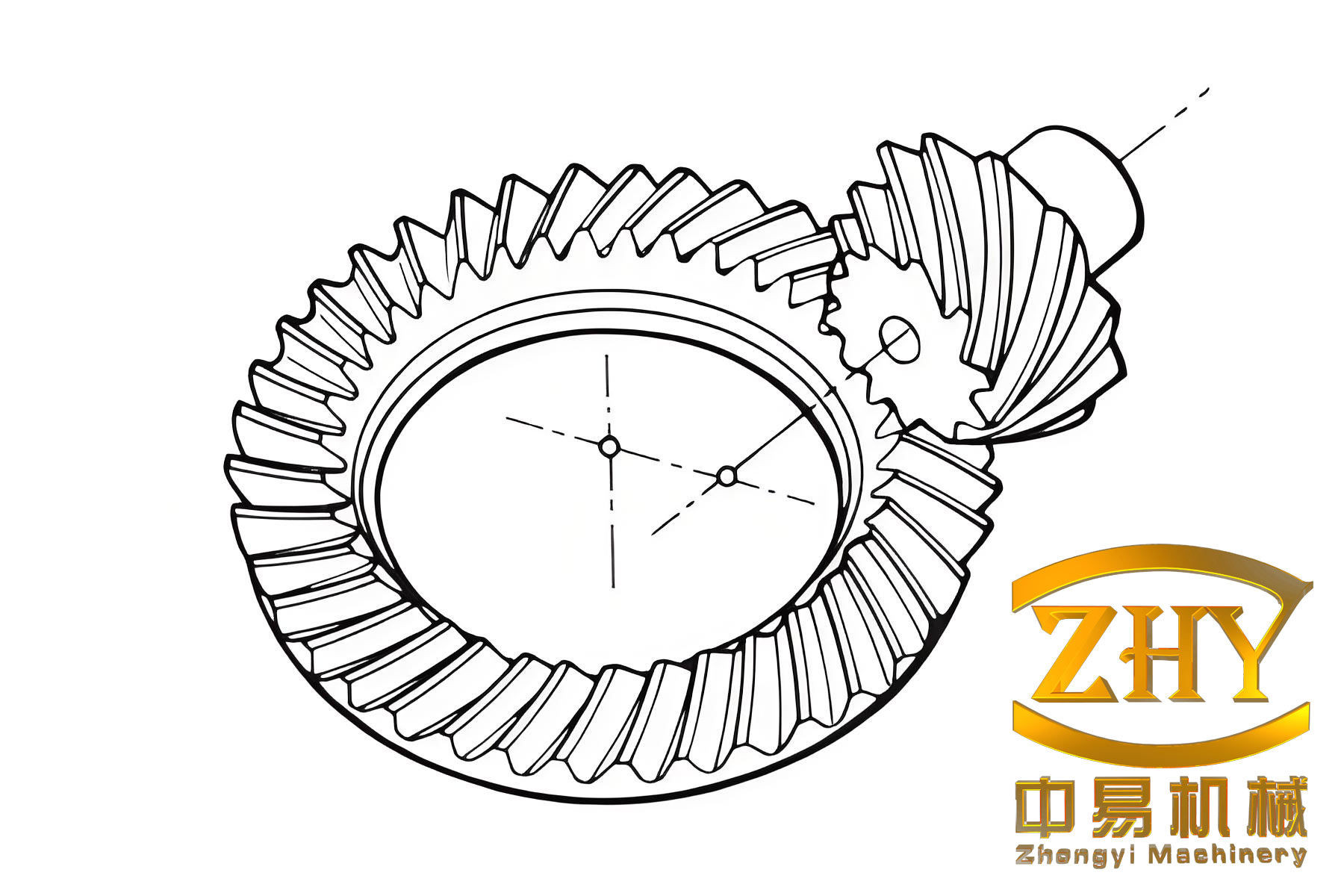
The core of the issue lies in the fundamentally different operating conditions between a hypoid bevel gear set (used in rear axle differentials) and the helical/spur gears found in most manual transmissions. The hypoid bevel gear configuration features a pinion axis that is offset from the crown wheel axis. This design allows for larger, stronger pinions, lower propeller shaft tunnels, and smoother operation. However, it introduces extreme levels of sliding friction in addition to rolling contact between the gear teeth.
The contact pressure on hypoid bevel gear teeth can be extreme, often exceeding 3,000 MPa (or 3 GPa). The sliding velocity can reach several meters per second. This combination generates very high localized instantaneous temperatures at the contact patch, estimated between 600°C to 1,000°C. Conventional anti-wear additives, which form protective layers through physical adsorption or mild chemical reaction, are desorbed and become ineffective well below these temperatures.
To prevent welding, scuffing, and rapid wear under these “Extreme Pressure” (EP) conditions, hypoid gear oils are fortified with specific EP additives containing reactive compounds of sulfur, phosphorus, and sometimes chlorine. These additives are designed to react chemically with the metal surface at the high flash temperatures of the contact zone, forming a sacrificial layer of metallic sulfide, phosphate, or chloride films.
$$ \text{Fe} + \text{R-S}_x \rightarrow \text{FeS} + \text{by-products} \quad \text{(at high flash temp)} $$
These films have a lower shear strength than the base metal, thus preventing metal-to-metal contact and allowing the gears to slide under immense load without catastrophic failure. This process is essentially a controlled, mild corrosion that prevents a more severe adhesive wear mode.
Manual transmission gears, typically involute helical or spur gears, operate under markedly different conditions. Tooth contact pressures are significantly lower (generally below 1.5 GPa), and the dominant motion is rolling with much less sliding. Operating temperatures are moderate, usually below 100°C. In this environment, the oil film, stabilized by anti-wear additives like Zinc Dialkyl Dithiophosphate (ZDDP), remains intact. Introducing a hypoid gear oil (GL-5) into this system is harmful. The aggressive EP additives, particularly the sulfur-based ones, are not quenched by high flash temperatures because such temperatures are not reached. Instead, they can slowly react with the gear and synchronizer surfaces, especially those made from copper alloys (e.g., brass synchronizer rings), leading to corrosive wear. Chlorine-based additives can hydrolyze in the presence of moisture, forming hydrochloric acid which further attacks metal surfaces.
The key differentiators are summarized in the table below:
| Parameter | Hypoid Bevel Gears (Rear Axle) | Transmission Gears (Helical/Spur) | Consequence of Misapplication |
|---|---|---|---|
| Primary Contact Motion | High-Pressure Sliding + Rolling | Predominantly Rolling + Some Sliding | GL-5 additives not activated; ineffective for intended purpose. |
| Tooth Contact Pressure | Extreme (> 3 GPa) | High, but lower (< 1.5 GPa) | |
| Flash Temperature | Very High (600-1000°C) | Moderate (< 100°C) | |
| Required Lubricant | GL-5 (High EP, Sulfur-Phosphorus) | GL-4 or GL-3 (Moderate EP, Anti-wear focus) | GL-5 causes corrosive wear on yellow metals & gear surfaces. |
| Critical Components at Risk | Gear teeth only. | Gear teeth & copper-alloy synchronizers. | Synchronizer ring corrosion leads to poor shifting. |
The performance of a lubricant is governed by the Stribeck curve, which plots the coefficient of friction against a parameter combining viscosity, speed, and load. EP additives shift the boundary lubrication regime to handle much higher loads. The incorrect oil places the transmission in an unfavorable region of this curve for its operating conditions.
$$ \Lambda = \frac{h_{min}}{R_q} $$
Where \(\Lambda\) is the specific film thickness, \(h_{min}\) is the minimum lubricant film thickness (a function of viscosity, speed, and load), and \(R_q\) is the composite surface roughness. For transmission gears, we aim for \(\Lambda > 3\) for full-film lubrication. Using a GL-5 oil does not significantly improve \(\Lambda\) but introduces chemically reactive components inappropriate for the lower-pressure, lower-temperature environment.
In conclusion, the recurrent failures in our vehicle starting systems stem from a definable set of mechanical, procedural, and material factors. Addressing them requires a disciplined approach: precise adjustment of the engagement mechanism, strict adherence to preventative maintenance schedules for the starter motor itself, operator re-training, and an upgrade to a more durable ring gear material. Parallel to this, it is crucial to maintain correct lubrication practices across all vehicle systems. The specialized, chemically active lubricants required for high-stress components like hypoid bevel gears in differentials must not be used as a universal substitute. Their unique formulation, while essential for protecting hypoid bevel gears under extreme pressure, can be actively damaging to other gear types operating under different tribological conditions. Adherence to manufacturer-specified lubricant standards for each subsystem is a fundamental pillar of effective vehicle maintenance and longevity.