
Gear hobbing belongs to the generating method, and its principle is equivalent to the meshing transmission of a pair of staggered shaft helical gears. During the meshing movement between the hob and the gear blank, the tooth surface is processed. When feeding along the gear axis, the whole tooth width can be processed, so as to obtain a complete gear.
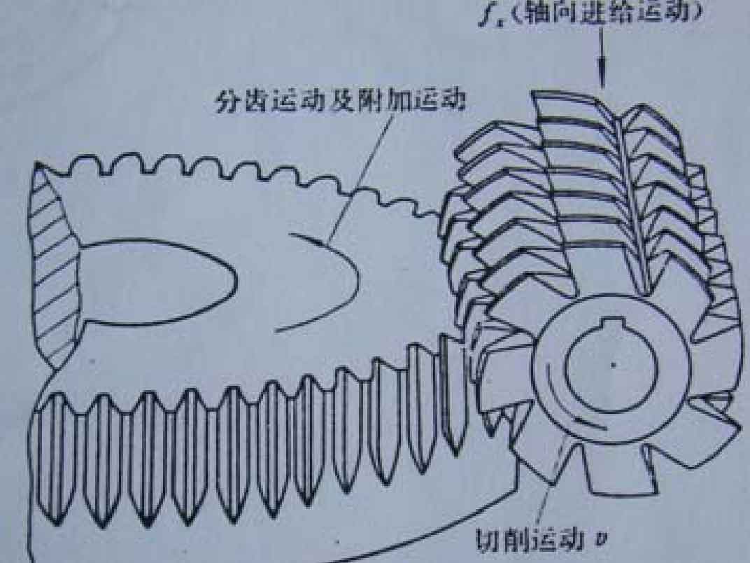
Hobbing spur gear includes the following first three movements (as shown in Figure 1):.
(1) Main cutting motion (main motion) the main motion is the rotary motion of the hob.
(2) The vertical feed movement is the vertical movement of the hob from top to bottom along the axis of the processed gear. The function of this movement is to ensure the complete tooth width.
(3) The rotary motion of the generating motion hob and the rotary motion of the machined gear constitute the generating motion of gear hobbing. The transmission ratio of the split change gear realizes the kinematic relationship between the gear hob and the machined gear.
(4) Differential indexing motion (used for hobbing helical gears) when hobbing helical cylindrical gears, in addition to the above three motions, because the tooth direction line of helical cylindrical gears is a helix, it must be realized by adding a composite motion. When the hob moves vertically along the axis of the added gear, the processed gear is required to generate an additional motion (i.e. turn a little more or a little less to form a helical tooth direction line) while developing the motion with the hob, and its motion relationship is realized by the transmission ratio of the differential change gear.
Gear hobbing is one of the main methods of gear machining. Processing helical gear with ordinary hobbing machine is similar to processing involute helical cylindrical gear, and also includes the above four movements. However, hobbing helical gear is different from hobbing involute helical cylindrical gear. It is necessary to design a reasonable fixture to change the position of surface gear blank on the hobbing machine. After clamping the fixture, The relative position between the hob and the face gear blank becomes: the vertical feed direction of the hob intersects vertically with the axis direction of the face gear, not parallel. Therefore, when hobbing helical gears, some improvements must be made to the existing ordinary hobbing machine. If a bevel gear transmission is added to make its transmission ratio 1:1, the purpose is to make the vertical feed direction of the hob vertically intersect with the axis direction of the face gear without changing the transmission ratio in the original transmission chain, and the processing part of the face gear changes from the cylindrical surface of the cylindrical blank to the end face. The schematic diagram of the transmission chain of the improved helical gear hobbing is shown in Figure 2.