
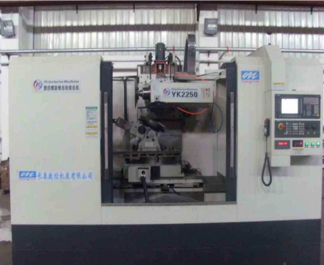
The evolution of gear milling technology for spiral bevel and hypoid gears represents a significant leap in manufacturing precision and flexibility. Traditional mechanical gear generators, characterized by their complex systems of cams, gears, and linkages to produce the requisite kinematic motions, are increasingly being superseded by Computer Numerical Control (CNC) platforms. This transition marks a frontier in advanced manufacturing, offering unparalleled advantages in accuracy, quality, and the ability to optimize tooth contact performance. Among the various established methods for producing these geometrically complex gears, the Tilted Cutter Semi-Generating method stands out for its effectiveness. A primary challenge and opportunity in modern gear production is the faithful replication and enhancement of such proven mechanical methods on new-generation CNC gear milling machines. This article delves into the methodologies for achieving this, focusing on the geometric and kinematic transformations required to implement the Tilted Cutter method on a state-of-the-art, multi-axis CNC spiral bevel gear milling machine.
The core of a CNC spiral bevel gear milling machine is the substitution of mechanical linkages with digitally coordinated servo axes. A representative architecture, such as the one illustrated, typically incorporates six fundamental CNC axes:
| Axis Designation | Description | Primary Function |
|---|---|---|
| X-axis | Horizontal linear motion of the cutter spindle/carriage. | Controls the radial distance of the cutter head relative to the workpiece center. |
| Y-axis | Vertical linear motion of the cutter spindle/carriage. | Controls the vertical offset, crucial for hypoid gear gear milling. |
| Z-axis | Linear motion of the workpiece along its own axis. | Provides the feed motion for depth-wise cutting. |
| A-axis (or B-axis) | Rotational motion of the workpiece spindle. | Governs the indexing and generating roll of the workpiece. |
| C-axis | Rotational motion of the cutter spindle. | Provides the primary cutting speed for the gear milling process. |
| B-axis (or A-axis) | Tilting motion of the workpiece spindle (machine root angle). | Sets the nominal angle between the workpiece and cutter axes. |
This configuration eliminates the need for physical components like the generating cradle, eccentric mechanism, and a mechanical cutter tilt mechanism. In a non-tilted (Basic) generating process, the root angle (B-axis) is fixed, and the cutter center follows a circular arc trajectory in the X-Y plane, perfectly emulating the motion of a traditional mechanical machine’s cradle. The fundamental challenge addressed here is: How can the Tilted Cutter method, which inherently requires a spatial inclination of the cutter axis relative to the theoretical generating gear, be reproduced on a machine that lacks a dedicated physical tilt mechanism? The solution lies in synthesizing the required spatial relationship between the cutter and workpiece through the simultaneous interpolation of the available CNC axes.
Geometric Principles of the Tilted Cutter Method
In the conventional Tilted Cutter Semi-Generating method applied on a mechanical machine, the spatial relationship between the cutter head (representing a tooth of the generating gear) and the imaginary generating gear is defined by a set of machine settings. Let us establish the key parameters in a coordinate system fixed to the theoretical generating gear (cradle).
Let \( O_c \) be the origin at the machine center (cradle center). The cutter head is characterized by its center point \( P_0 \) and its axis vector \( \mathbf{a} \). The workpiece (pinion) is represented by its apex point \( P_w \) and its axis vector \( \mathbf{w} \). The standard machine settings for the tilted cutter method are:
- Radial Distance (\( S_R \)): The distance from the machine center \( O_c \) to the cutter center \( P_0 \).
- Angular Position (\( q \)): The angle of the vector \( O_c P_0 \) relative to the machine horizontal plane.
- Cutter Tilt Angle (\( i \)): The angle between the cutter axis \( \mathbf{a} \) and the generating gear axis \( \mathbf{z}_c \). This is the total tilt.
- Basic Cutter Swivel Angle (\( j \)): The direction of the projection of the cutter axis \( \mathbf{a} \) onto a plane perpendicular to \( \mathbf{z}_c \), measured from the radial direction \( O_c P_0 \).
- Workpiece Mounting Distance (\( \Delta X \)) and Offset (\( \Delta E \)).
- Workpiece Root Angle (\( \gamma_m \)).
The coordinates of the cutter center \( P_0 \) and the cutter axis vector \( \mathbf{a} \) in the cradle coordinate system are derived from these settings:
$$
P_0 = \begin{bmatrix}
S_R \cos q \\
S_R \sin q \\
0
\end{bmatrix}, \quad \mathbf{a} = \begin{bmatrix}
\cos i \cos(q + j) \\
\cos i \sin(q + j) \\
\sin i
\end{bmatrix}
$$
The workpiece apex \( P_w \) and its axis vector \( \mathbf{w} \) are given by:
$$
P_w = \begin{bmatrix}
\Delta X \\
-\Delta E \sin \gamma_m \\
\Delta E \cos \gamma_m
\end{bmatrix}, \quad \mathbf{w} = \begin{bmatrix}
0 \\
\sin \gamma_m \\
\cos \gamma_m
\end{bmatrix}
$$
During the generating roll, the cradle angle \( \phi_c \) (and consequently the angular position \( q \)) varies. The relationship between the workpiece roll angle \( \phi_w \) and the cradle roll angle \( \phi_c \) is defined by the ratio of roll \( R_{roll} \): \( \phi_w = R_{roll} \cdot \phi_c \). For each infinitesimal step in the process, these vectors define the instantaneous spatial relationship between the tool and the generating gear.
Kinematic Transformation for CNC Gear Milling
The CNC gear milling machine does not have a cradle. Its reference frame is typically attached to the machine bed, with the workpiece rotation center (the intersection point of the workpiece axis and the B-axis tilt center) as a key fixed point. To replicate the Tilted Cutter method, we must ensure that the invariant geometric relationships between the cutter and the workpiece are preserved at every instant during the machining cycle. These invariants are:
- The angle between the cutter axis \( \mathbf{a} \) and the workpiece axis \( \mathbf{w} \).
- The shortest distance (center distance) between the cutter axis \( \mathbf{a} \) and the workpiece axis \( \mathbf{w} \).
- The distances from a fixed point on the workpiece (e.g., its apex \( P_w \)) and a fixed point on the cutter axis (e.g., the cutter center \( P_0 \)) to the common perpendicular line connecting the two skew axes.
Let us denote these invariants mathematically. The angle \( \Sigma \) between the axes is given by their dot product:
$$
\cos \Sigma = \mathbf{a} \cdot \mathbf{w}
$$
The vector \( \mathbf{n} \) of the common perpendicular and the center distance \( C_d \) can be found using the cross product:
$$
\mathbf{n} = \mathbf{a} \times \mathbf{w}, \quad C_d = \frac{| (\mathbf{r}_w – \mathbf{r}_a) \cdot \mathbf{n} |}{|\mathbf{n}|}
$$
where \( \mathbf{r}_a \) and \( \mathbf{r}_w \) are position vectors of points on the cutter and workpiece axes, respectively (e.g., \( P_0 \) and \( P_w \)).
The distances \( L_w \) and \( L_a \) from the fixed points \( P_w \) and \( P_0 \) to the foot of the common perpendicular are computed via vector projection. For a given cradle roll angle \( \phi_c \) in the traditional system, these three invariants \( (\Sigma, C_d, L_w, L_a) \) have specific numeric values.
On the CNC gear milling machine, we establish a machine coordinate system (MCS) with its origin \( O_m \) at the intersection of the workpiece axis and the B-axis rotation center. The Z-axis of the MCS is aligned with the workpiece axis when the B-axis angle \( \beta \) is zero. The X-Y plane is parallel to the plane defined by the machine’s X and Y linear axes. In this MCS, the workpiece apex \( P’_w \) and axis \( \mathbf{w}’ \) are defined by the machine’s setup parameters (e.g., sliding base setting). The cutter center position \( P’_0 = [X, Y, 0]^T \) is directly commanded by the X and Y axes. The cutter axis vector \( \mathbf{a}’ \) is nominally vertical \( [0, 0, 1]^T \) in the MCS when no synthetic tilt is applied.
The key to implementing the tilt is to manipulate the machine’s B-axis (workpiece tilt angle \( \beta \)) and the X-Y coordinates simultaneously to create an effective cutter tilt relative to the workpiece. For a desired instantaneous relationship defined by the invariants from the traditional method, we must solve for the corresponding CNC machine coordinates \( (X, Y, \beta, \phi_w) \).
The condition for the axis angle \( \Sigma \) becomes a function of the machine B-axis angle \( \beta \). In the MCS, the workpiece axis vector is \( \mathbf{w}’ = [-\sin \beta, 0, \cos \beta]^T \) (assuming tilt around the Y-axis). The cutter axis remains \( \mathbf{a}’ = [0, 0, 1]^T \). Their dot product gives:
$$
\mathbf{a}’ \cdot \mathbf{w}’ = \cos \beta
$$
Equating this to the invariant from the traditional system, \( \mathbf{a} \cdot \mathbf{w} = \cos \Sigma \), yields the fundamental relationship for the machine tilt angle:
$$
\cos \beta = \cos \Sigma \quad \Rightarrow \quad \beta = \Sigma
$$
(Considering the sign convention for the angle). This elegantly shows that the machine’s root angle \( \beta \) must be dynamically adjusted to equal the instantaneous axis crossing angle \( \Sigma \) from the tilted cutter method. \( \Sigma \) itself varies during the generating roll because the cutter axis vector \( \mathbf{a} \) changes orientation relative to the fixed workpiece axis \( \mathbf{w} \) in the traditional setup. Therefore, \( \beta \) is no longer a constant but a function of the roll position \( \phi_c \): \( \beta(\phi_c) \).
Next, we must ensure the center distance \( C_d \) and the distances \( L_w, L_a \) are correct. In the CNC MCS, with the workpiece tilted by \( \beta \), the coordinates of the workpiece apex \( P’_w \) and axis \( \mathbf{w}’ \) are known. The cutter center \( P’_0 = (X, Y, 0) \) and axis \( \mathbf{a}’ = (0,0,1) \) are our unknowns (X and Y). We can formulate equations for the invariants \( C_d \), \( L_w \), and \( L_a \) within the MCS, using expressions analogous to those used in the traditional system but with our MCS vectors.
Let \( \mathbf{r}’_w \) be the position of the workpiece apex in MCS and \( \mathbf{r}’_a = [X, Y, 0]^T \). The common perpendicular vector in MCS is \( \mathbf{n}’ = \mathbf{a}’ \times \mathbf{w}’ \). The equations become:
1. Center Distance Invariance:
$$
\frac{| (\mathbf{r}’_w – \mathbf{r}’_a) \cdot \mathbf{n}’ |}{|\mathbf{n}’|} = C_d(\phi_c)
$$
2. Workpoint Distance Invariance (for workpiece apex):
The distance \( L’_w \) from \( P’_w \) to the foot of the common perpendicular in MCS must equal \( L_w(\phi_c) \). This distance can be expressed as the magnitude of the projection of \( (\mathbf{r}’_w – \mathbf{r}’_a) \) onto a plane, leading to a specific scalar equation.
3. Cutter Center Distance Invariance:
Similarly, the distance \( L’_a \) from \( P’_0 \) to the foot of the common perpendicular in MCS must equal \( L_a(\phi_c) \).
For a given \( \phi_c \), we have already determined \( \beta \). The unknowns are the cutter center coordinates \( X \) and \( Y \). The three invariant conditions provide more than enough constraints to solve for X and Y. In practice, solving the system formed by the center distance equation and one of the point-distance equations is sufficient. The solution yields the required synchronized motion path for the X and Y axes: \( X(\phi_c) \) and \( Y(\phi_c) \).
Finally, the workpiece rotational position \( \phi_w \) (A-axis) is governed by the same ratio of roll as in the traditional method: \( \phi_w(\phi_c) = R_{roll} \cdot \phi_c \).
Thus, the complete CNC motion program for replicating the Tilted Cutter Semi-Generating method is defined by four synchronized functions of the generating roll parameter \( \phi_c \):
$$
\begin{align*}
\text{X-axis:} & \quad X(\phi_c) \\
\text{Y-axis:} & \quad Y(\phi_c) \\
\text{B-axis:} & \quad \beta(\phi_c) = \Sigma(\phi_c) \\
\text{A-axis:} & \quad \phi_w(\phi_c) = R_{roll} \cdot \phi_c
\end{align*}
$$
The Z-axis provides the feed motion independently, and the C-axis provides constant cutter spindle speed.
| Traditional Mechanical Parameter | Corresponding CNC Axis Motion | Transformation Principle |
|---|---|---|
| Cradle Roll (\(\phi_c\)) | Not a physical axis. Serves as the independent motion parameter. | The entire kinematic chain is parameterized by this virtual angle. |
| Radial (\(S_R\)) & Angular (\(q\)) Settings | Synchronized X(\(\phi_c\)) and Y(\(\phi_c\)) linear motions. | Solved from invariant geometric conditions (center distance, workpoint locations). |
| Cutter Tilt Angle (\(i\)) & Swivel (\(j\)) | Dynamic B-axis tilt \(\beta(\phi_c)\). | \(\beta\) is set equal to the instantaneous crossing angle \(\Sigma\), which is a function of \(i\), \(j\), and \(q(\phi_c)\). |
| Workpiece Roll (\(\phi_w\)) | A-axis rotation \(\phi_w(\phi_c)\). | Direct mapping via the ratio of roll: \(\phi_w = R_{roll} \cdot \phi_c\). |
Advantages and Implications for Gear Milling
The implementation of the Tilted Cutter method via CNC axis interpolation, as described, unlocks significant benefits for modern gear milling:
- Elimination of Mechanical Limitations: The need for physical cutter tilt brackets, swivel mechanisms, and complex cradle drives is removed. This simplifies machine structure, reduces maintenance, and improves static and dynamic stiffness, leading to more accurate gear milling.
- Enhanced Flexibility and Process Optimization: The tilt angle \(\beta\) and cutter path \((X, Y)\) are now freely programmable functions. This allows for:
- Easy implementation of Modified Roll techniques for contact pattern optimization.
- Exploration of non-standard, higher-order motion laws to correct errors or induce specific tooth surface modifications.
- Rapid changeover between different gear designs by simply loading a new NC program, without mechanical change gears or settings.
- Improved Accuracy: CNC interpolation eliminates errors associated with wear and backlash in mechanical generating trains. The position of each axis is directly measured and controlled by high-resolution feedback devices.
- Foundation for Advanced Methods: This mathematical framework for mapping traditional settings to CNC motions is not limited to the Tilted Cutter method. It can be extended to other systems like Formate, Duplex Helix, or even to synthesize entirely new gear milling strategies that were impossible on mechanical machines.
The synthesis of the toolpath requires sophisticated software based on the precise mathematical models of gear geometry and machine kinematics. The core calculation involves solving the system of nonlinear equations derived from the invariant conditions for each discretized step along the generating roll. This is computationally intensive but well within the capability of modern PC-based CNC systems. The output is a standard NC code (e.g., G-code) that commands the synchronized movement of the X, Y, Z, A, B, and C axes.
In conclusion, the reproduction of the Tilted Cutter Semi-Generating method on a CNC spiral bevel gear milling machine is a quintessential example of digital transformation in precision manufacturing. It involves decomposing the holistic mechanical setup into fundamental geometric invariants and then reconstructing the required spatial relationship through the coordinated motion of programmable servo axes. This approach not only preserves the proven capabilities of traditional gear milling but also transcends them, offering a platform for unprecedented levels of precision, flexibility, and innovation in the production of spiral bevel and hypoid gears. The mastery of this transformation is crucial for the full exploitation of advanced CNC gear milling technology, enabling independent development of cutting processes and moving beyond reliance on proprietary vendor software.