
In our professional gear manufacturing facility, we specialize in producing a wide range of gears for automotive, diesel engine, tractor, transmission, and engineering machinery applications, with a significant focus on spiral bevel gears. Due to a recent surge in production demand, our existing box furnaces became insufficient to meet the required output. To enhance productivity and fulfill orders, we decided to transition a portion of our spiral bevel gear production to pit furnaces. However, this shift presented two critical challenges: first, the pit furnaces lacked a carbon potential control system, leading to inconsistent metallurgical properties in the gears; second, using conventional fixtures resulted in excessive and unpredictable distortion during quenching, which caused irregular contact patterns during gear pairing in the machining workshop. To address these issues, we implemented targeted improvements through custom fixture design and equipment upgrades, ensuring product quality and顺利完成 production targets.
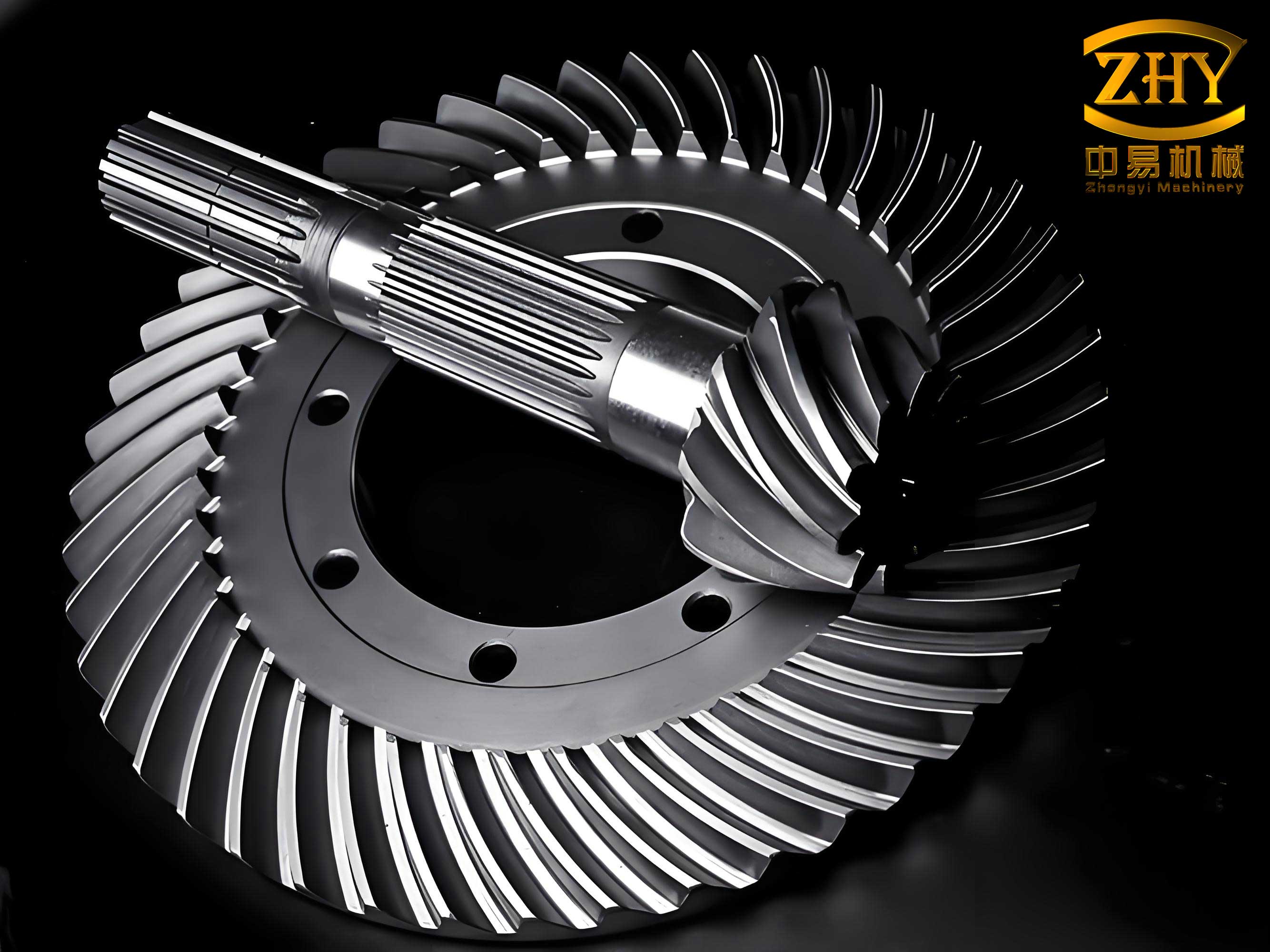
The core of our approach involved designing specialized fixtures based on the unique characteristics of spiral bevel gears and principles of thermal equilibrium. Spiral bevel gears, known for their curved teeth that enable smooth and efficient torque transmission, require precise heat treatment to maintain dimensional stability and hardness. Our fixture designs aimed to minimize distortion by ensuring uniform heating and cooling. For the driven spiral bevel gears, we developed a fixture with welded lifting lugs and support columns, along with insertable positioning pins to secure the gears during processing. For the driving spiral bevel gears, we employed a two-tier fixture with perforated plates to enhance gas permeability and oil flow during quenching, promoting even cooling. These fixtures were constructed using heat-resistant cast steel, such as ZG35Cr24Ni7SiN (approximate equivalent to ASTM HH type), which offered excellent durability and minimal deformation over extended use. The results were significant: distortion was reduced to within 0.1–0.3 mm at the outer edges and 0.1–0.2 mm at the inner edges, with over 90% of gears meeting drawing specifications. Moreover, contact patterns during pairing became consistent and predictable, greatly improving assembly efficiency.
To further elaborate, the thermal equilibrium theory guided our fixture design. This theory emphasizes balancing heat input and output to prevent localized stresses that cause distortion. For spiral bevel gears, the complex geometry necessitates careful consideration of heat flow during carburizing and quenching. We can express the heat balance during quenching using the following equation for transient heat conduction:
$$ \rho C_p \frac{\partial T}{\partial t} = \nabla \cdot (k \nabla T) + q $$
where \( \rho \) is density, \( C_p \) is specific heat capacity, \( T \) is temperature, \( t \) is time, \( k \) is thermal conductivity, and \( q \) represents internal heat generation (negligible during quenching). For uniform cooling, we aimed to minimize temperature gradients, which reduces thermal stresses described by:
$$ \sigma_{thermal} = E \alpha \Delta T $$
where \( E \) is Young’s modulus, \( \alpha \) is the coefficient of thermal expansion, and \( \Delta T \) is the temperature difference across the gear. By optimizing fixture design to promote symmetric heat dissipation, we kept \( \Delta T \) low, thereby controlling distortion in spiral bevel gears.
Following fixture implementation, we observed that while distortion was under control, metallurgical quality occasionally fell short due to uncontrolled carbon potential in the pit furnaces. To resolve this, we integrated an advanced carbon potential and temperature control system from a specialized provider. The system featured a programmable controller with PID algorithms and RS-485 communication interfaces, allowing seamless integration with existing furnace controls. The oxygen probe, utilizing a robust zirconia-based sensor with vacuum-sealed construction, offered fast response times and long service life. Carbon potential (\( C_p \)) is related to the oxygen probe output (EMF, \( E \)) by the Nernst equation:
$$ E = \frac{RT}{4F} \ln \left( \frac{P_{O_2,\text{air}}}{P_{O_2,\text{furnace}}} \right) $$
where \( R \) is the gas constant, \( T \) is absolute temperature, \( F \) is Faraday’s constant, \( P_{O_2,\text{air}} \) is the partial pressure of oxygen in air (0.209 atm), and \( P_{O_2,\text{furnace}} \) is the partial pressure in the furnace atmosphere. For carburizing processes, carbon potential can be derived from equilibrium constants involving CO and CO₂, but in practice, the controller uses empirical correlations to maintain desired levels. By automating carbon potential control, we ensured consistent case depth and microstructure in spiral bevel gears.
To summarize our improvements, below are tables detailing key parameters and results. Table 1 outlines typical specifications for the spiral bevel gears we produce, highlighting their diversity in size and application. Table 2 provides design parameters for our custom fixtures, emphasizing features that address distortion. Table 3 lists optimized carburizing and quenching工艺 parameters for pit furnaces, incorporating carbon potential control. Table 4 compares distortion data before and after improvements, demonstrating the efficacy of our approach.
| Gear Type | Module (mm) | Outer Diameter (mm) | Material | Application |
|---|---|---|---|---|
| Driven Spiral Bevel Gear | 4-10 | 200-500 | 20CrMnTi | Automotive Rear Axle |
| Driving Spiral Bevel Gear | 3-8 | 150-400 | 20CrMo | Engineering Machinery |
| Spiral Bevel Gear Set | 5-12 | 300-600 | SAE 8620 | Industrial Transmissions |
| Fixture Component | Material | Design Feature | Purpose |
|---|---|---|---|
| Lifting Lugs | Welded Steel | Reinforced Welding | Secure handling during processing |
| Support Columns | Heat-Resistant Cast Steel | Adjustable Height | Minimize gear contact points to reduce thermal mass |
| Positioning Pins | Insertable Alloy Pins | Removable Design | Prevent gear movement during carburizing |
| Perforated Plates | ZG35Cr24Ni7SiN | Square Holes (20 mm x 20 mm) | Enhance atmosphere circulation and oil quenching efficiency |
The carburizing process for spiral bevel gears involves diffusing carbon into the surface at elevated temperatures to achieve a hard, wear-resistant case. The case depth (\( d \)) can be estimated using Fick’s second law of diffusion:
$$ d = \sqrt{D t} $$
where \( D \) is the diffusion coefficient of carbon in steel, which depends on temperature via the Arrhenius equation \( D = D_0 \exp(-Q/RT) \), with \( D_0 \) as a pre-exponential factor and \( Q \) as activation energy. By controlling carbon potential, we maintained a consistent surface carbon concentration (typically 0.8-1.0 wt%) for optimal hardness in spiral bevel gears.
| Process Stage | Temperature (°C) | Time (hours) | Carbon Potential (wt% C) | Atmosphere Composition |
|---|---|---|---|---|
| Heating | 850-900 | 1-2 | 0.8-0.9 | Endothermic gas (N₂ + CH₄) |
| Carburizing | 920-940 | 4-8 | 1.0-1.2 | Enriched endothermic gas with propane |
| Diffusion | 920-940 | 1-2 | 0.8-0.9 | Balanced endothermic gas |
| Quenching | 830-850 (austenitizing) | 0.5-1 | N/A | Fast oil quench at 60-80°C |
| Tempering | 180-200 | 2-3 | N/A | Air |
After implementing these改进, we monitored gear quality over an extended period. The custom fixtures significantly reduced distortion, as quantified in Table 4. For spiral bevel gears, distortion is critical because it affects meshing performance and noise levels. The contact pattern consistency improved, with over 95% of gears showing optimal印痕 alignment during配对. Additionally, the carbon control system eliminated metallurgical defects such as excessive carbide networks or soft spots, ensuring that spiral bevel gears met stringent automotive standards.
| Gear Type | Measurement Location | Distortion Before (mm) | Distortion After (mm) | Reduction (%) |
|---|---|---|---|---|
| Driven Spiral Bevel Gear | Outer Edge (Tooth Tip) | 0.5-0.8 | 0.1-0.3 | ~70 |
| Driven Spiral Bevel Gear | Inner Edge (Bore) | 0.4-0.6 | 0.1-0.2 | ~75 |
| Driving Spiral Bevel Gear | Outer Edge | 0.6-1.0 | 0.2-0.4 | ~65 |
| Driving Spiral Bevel Gear | Inner Edge | 0.5-0.9 | 0.15-0.25 | ~70 |
The economic impact of these improvements has been substantial. By increasing the yield of合格 spiral bevel gears and reducing rework, we achieved a 20% boost in overall production efficiency. The longevity of the fixtures, lasting over two years without significant deformation, minimized downtime and maintenance costs. Furthermore, the enhanced product consistency strengthened our reputation in the market, leading to increased orders for spiral bevel gears across various sectors.
In conclusion, the integration of custom-designed fixtures based on thermal equilibrium principles and advanced carbon potential control systems has transformed our pit furnace operations for spiral bevel gear heat treatment. This holistic approach addresses both distortion and metallurgical quality, resulting in reliable, high-performance gears. The success of this project underscores the importance of tailored solutions in manufacturing, particularly for complex components like spiral bevel gears. As we continue to refine our processes, we aim to further optimize parameters using computational modeling, such as finite element analysis for heat treatment simulations, to push the boundaries of quality and efficiency in spiral bevel gear production.
To delve deeper into the理论, the thermal平衡 during quenching can be modeled using numerical methods. For instance, the cooling rate (\( \frac{dT}{dt} \)) influences phase transformations in steel, affecting hardness and residual stresses. The martensite start temperature (\( M_s \)) for spiral bevel gear materials can be estimated using empirical formulas like:
$$ M_s (\degree C) = 539 – 423C – 30.4Mn – 17.7Ni – 12.1Cr – 7.5Mo $$
where element symbols represent weight percentages. By controlling quenching parameters, we ensure that spiral bevel gears achieve a fully martensitic case with minimal retained austenite. Additionally, the carbon potential control system allows for precise adjustment of case depth according to gear design requirements. For example, deeper cases are needed for heavily loaded spiral bevel gears in off-road vehicles, while shallower cases suffice for lighter applications. This flexibility has enabled us to customize heat treatment for diverse spiral bevel gear variants.
Looking ahead, we plan to explore advanced monitoring techniques, such as in-situ sensors for real-time distortion measurement during quenching, to further enhance process control for spiral bevel gears. The lessons learned from this improvement initiative have also been applied to other gear types, but the focus remains on perfecting the工艺 for spiral bevel gears due to their critical role in power transmission systems. Through continuous innovation and adherence to quality principles, we are confident in maintaining our leadership in gear manufacturing, with spiral bevel gears as a cornerstone of our product portfolio.