
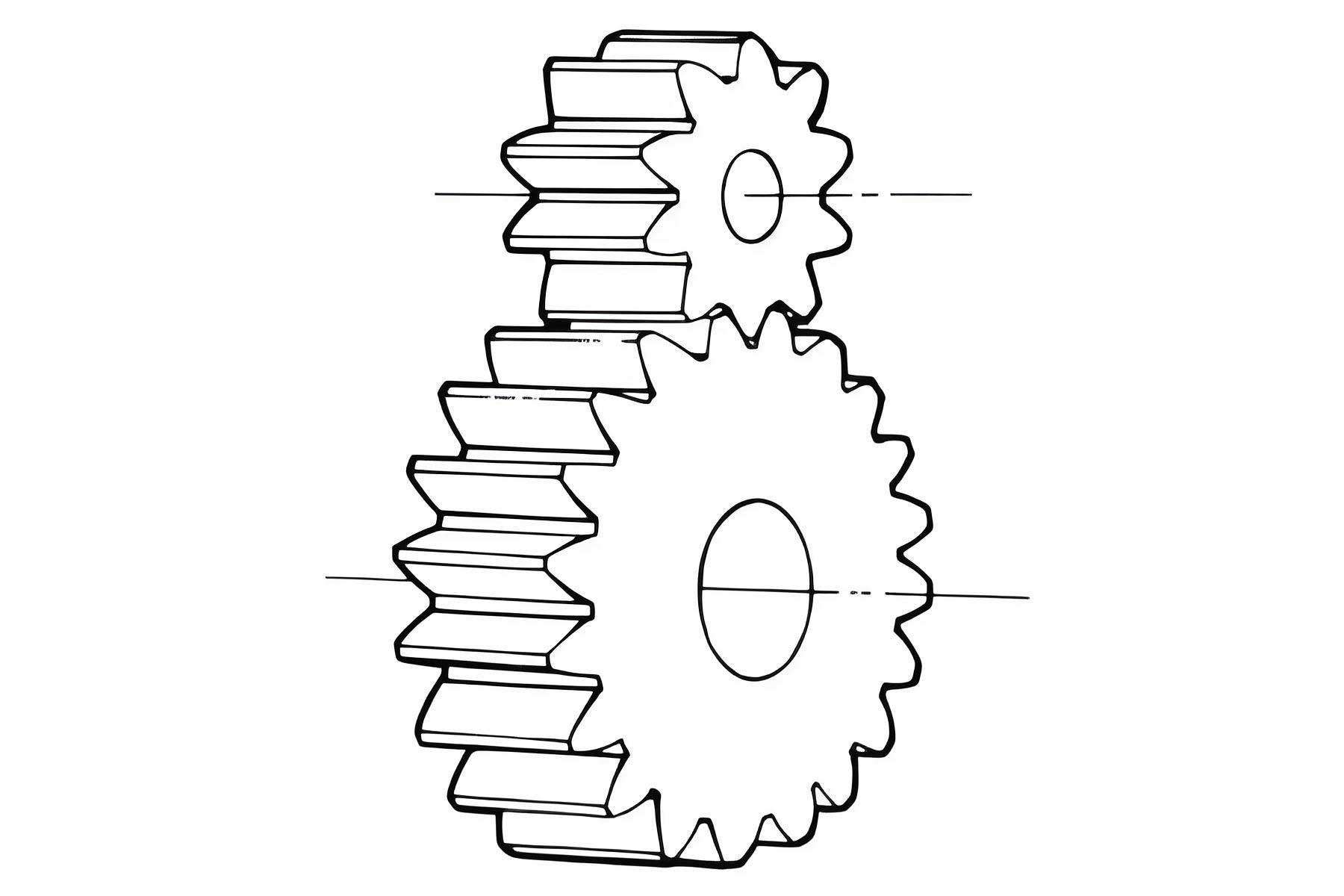
The pursuit of exceptionally smooth and quiet operation in precision power transmission systems, such as those employed in astronomical telescopes and high-end instrumentation, places stringent demands on gear performance. Among various gear types, the spur gear remains fundamental due to its simplicity and effectiveness in parallel shaft applications. However, the inherent kinematic characteristics of unmodified spur gears, combined with manufacturing imperfections and load-induced deformations, can lead to significant fluctuations in transmission error, resulting in vibration and acoustic noise. This work presents a comprehensive methodology for the integrated design of profile modification and the compensation for pitch errors, specifically targeting the minimization and smoothing of the static transmission error (STE) curve in precision spur gear pairs.
The central challenge in precision gearing is to manage the Static Transmission Error (STE), defined as the difference between the actual angular position of the output gear and its theoretical position for a given input angle, under loaded conditions. The STE, denoted as $\Delta \phi_2(\phi_1)$, is a primary source of gear mesh excitation. It arises from two main components: the geometric or manufacturing transmission error (MTE) under no-load conditions, and the additional error induced by elastic deflections of the teeth under operating torque. A non-smooth STE curve with abrupt changes or large amplitude fluctuations directly translates to undesirable dynamic forces.
Profile modification, the intentional deviation of the tooth flank from the theoretical involute form, is a well-established technique to improve meshing conditions. Traditional approaches often define modification parameters along the line of action. In contrast, this methodology innovatively defines the pre-designed, no-load Manufacturing Transmission Error (MTE) curve itself as the direct descriptor for profile modification. This approach intrinsically links the modification geometry to the desired kinematic performance before loading. Furthermore, while prior studies often treat profile modification in isolation, practical high-precision spur gears invariably possess manufacturing errors, with pitch error being one of the most critical. Isolated optimization without considering these errors can lead to suboptimal performance. Therefore, an integrated design that simultaneously addresses both systematic profile modification and random pitch errors is essential for achieving the smoothest possible STE.
Theoretical Foundations: Transmission Error and Contact
The kinematic and static performance of a gear mesh is governed by the principles of Tooth Contact Analysis (TCA) and load distribution. The fundamental equation for the total Static Transmission Error (STE) can be expressed as a superposition:
$$ \Delta \phi_{2}^{STE}(\phi_1) = \Delta \phi_{2}^{MTE}(\phi_1) + \Delta \phi_{2}^{Load}(\phi_1) $$
where:
- $\Delta \phi_{2}^{STE}(\phi_1)$ is the total static transmission error.
- $\Delta \phi_{2}^{MTE}(\phi_1)$ is the no-load manufacturing transmission error, stemming from profile modifications and geometric errors like pitch deviations.
- $\Delta \phi_{2}^{Load}(\phi_1)$ is the component caused by the elastic deflection of the mating teeth under the specified torque. This value is typically negative, indicating a lag in the output position due to compliance.
The Manufacturing Transmission Error for a modified spur gear pair is calculated using TCA theory. The core condition for contact is the coincidence of position vectors and the collinearity of surface normals at the contact point. For two gear surfaces $\mathbf{r}^{(1)}(u_1, \theta_1)$ and $\mathbf{r}^{(2)}(u_2, \theta_2)$, the system of equations is:
$$
\begin{aligned}
\mathbf{r}^{(1)}(u_1, \theta_1) – \mathbf{r}^{(2)}(u_2, \theta_2) &= 0 \\
\mathbf{n}^{(1)}(u_1, \theta_1) – \lambda \mathbf{n}^{(2)}(u_2, \theta_2) &= 0
\end{aligned}
$$
Solving this system for the output rotation $\phi_2$ as a function of the input rotation $\phi_1$ yields the MTE curve, $\Delta \phi_{2}^{MTE}(\phi_1) = \phi_2(\phi_1) – (N_1/N_2)\phi_1$, where $N_1$ and $N_2$ are the tooth numbers of the driving and driven spur gears, respectively.
Geometric Modeling of Modified Spur Gear Teeth
Definition of Profile Modification Parameters
Departing from conventional definitions, the profile modification is parameterized directly by the intended no-load transmission error curve. A symmetric, piecewise function is chosen for the design MTE. The curve consists of a central zone of zero error (perfect conjugation) flanked by two modification zones, typically modeled with power functions to ensure smooth transitions.
$$ \Delta \phi_2^{Design}(\phi_1) =
\begin{cases}
a \cdot (\phi_1 – \theta_1)^b & \phi_1 \geq \theta_1 \\
0 & \theta_2 < \phi_1 < \theta_1 \\
a \cdot (-\phi_1 + \theta_2)^b & \phi_1 \leq \theta_2
\end{cases} $$
Here, $\theta_1$ and $\theta_2$ define the angular positions on the input gear where modification begins (the boundaries of the zero-error zone). Due to symmetry, $\theta_0 = (\theta_1 + \theta_2)/2$ marks the pitch point, and $\theta_2 = 2\theta_0 – \theta_1$. The parameters $a$ and $b$ control the amplitude and shape of the modification curve. Therefore, the set $(\theta_1, a, b)$ fully defines the modification and is the target of the optimization process for the spur gear.
Tooth Flank Equation with Pitch Error
The mathematical model of the tooth flank must account for cumulative pitch errors. Starting with the basic involute equation for a standard right-hand spur gear tooth $i=0$ in its local coordinate system $(S_w)$:
$$ \mathbf{r}_w(v_w) = \begin{bmatrix} r_{bw}(\sin(v_w) – v_w \cos(v_w)) \\ r_{bw}(\cos(v_w) + v_w \sin(v_w)) \\ 0 \\ 1 \end{bmatrix} $$
where $r_{bw}$ is the base radius and $v_w$ is the roll angle. The modified pinion flank is generated virtually by simulating the meshing of this basic rack (or cutter) with the desired MTE. This yields the modified pinion profile $\mathbf{r}_{p,h}(\phi_1, a, b, \theta_1)$.
To assemble the complete gear in a global coordinate system $(S_q)$, coordinate transformations incorporating the gear rotation and pitch errors are applied. The transformation matrices for rotation about the Z-axis and translation along the X-axis are:
$$ \mathbf{R}_z(\theta) = \begin{bmatrix} \cos(\theta) & \sin(\theta) & 0 & 0 \\ -\sin(\theta) & \cos(\theta) & 0 & 0 \\ 0 & 0 & 1 & 0 \\ 0 & 0 & 0 & 1 \end{bmatrix}, \quad \mathbf{T}_x(S) = \begin{bmatrix} 1 & 0 & 0 & -S \\ 0 & 1 & 0 & 0 \\ 0 & 0 & 1 & 0 \\ 0 & 0 & 0 & 1 \end{bmatrix} $$
Considering the center distance $a_0$, the surface of the $i$-th tooth (where $i=0$ is the first tooth) of the driven wheel and the driving pinion in the global system are:
$$
\begin{aligned}
\mathbf{r}_{q,w}^{(i)}(\phi_w) &= \mathbf{R}_z(\pi) \mathbf{T}_x(a_0) \mathbf{R}_z(-\phi_w) \mathbf{R}_z(-(i\cdot \frac{2\pi}{N_w} + \gamma_{w,i})) \mathbf{r}_w \\
\mathbf{r}_{q,p}^{(i)}(\phi_p) &= \mathbf{R}_z(\phi_p) \mathbf{R}_z(-(i\cdot \frac{2\pi}{N_p} + \gamma_{p,i})) \mathbf{r}_{p,h}
\end{aligned}
$$
where $\phi_w$ and $\phi_p$ are the global rotation angles, $N_w$ and $N_p$ are tooth numbers, and $\gamma_{w,i}$, $\gamma_{p,i}$ are the cumulative pitch angle errors for the $i$-th tooth of the wheel and pinion, respectively. This model is essential for performing TCA on gears with realistic manufacturing errors.
Design for Spur Gears Without Pitch Error
The initial step is to derive the optimal profile modification parameters for an ideal spur gear pair with no pitch errors, subject to a specified constant load torque. The goal is to minimize the peak-to-peak amplitude of the resulting STE curve.
Under load, the single tooth pair deflection $\delta_0$ at the pitch point $\theta_0$ and the deflection $\delta_3$ at the start of the theoretical double-tooth contact zone $\theta_3$ are critical. For minimal STE fluctuation, the total STE at points $\theta_0$ and $\theta_3$ should be equal. This condition, combined with the fact that the designed MTE at $\theta_0$ is zero and at $\theta_3$ is $\epsilon = a(\theta_3 – \theta_1)^b$, leads to the following constraint equation:
$$ 0 + \delta_0 = \epsilon + \delta_3 $$
$$ \delta_0 = a(\theta_3 – \theta_1)^b + \delta_3 $$
Furthermore, the maximum value of the designed MTE, $\Delta\phi_{2,max}$, typically occurs near the tooth tip and must not exceed the compensation capacity provided by the load deflection at that point to avoid edge contact. Assuming symmetric design and utilizing the geometric relationship $\theta_3 – \theta_1 = (\theta_4 – \theta_3)$, where $\theta_4$ is the meshing-in point for the next tooth, the exponent $b$ can be solved analytically:
$$ b = \log_2\left(\frac{\delta_0}{\delta_0 – \delta_3}\right) $$
The values for $\delta_0$ and $\delta_3$ are obtained from Finite Element Analysis (FEA) of the unmodified gear pair under the specified torque at the relevant contact positions. With $b$ determined, parameter $a$ can be calculated from the first constraint equation, and $\theta_1$ is chosen based on contact ratio and the desired length of the unmodified zone.
| Design Goal | Governing Condition | Derived Parameter Formula | Required Input |
|---|---|---|---|
| Minimize STE Amplitude | $\Delta \phi_{2}^{STE}(\theta_0) = \Delta \phi_{2}^{STE}(\theta_3)$ | $b = \log_2\left(\frac{\delta_0}{\delta_0 – \delta_3}\right)$ | $\delta_0$, $\delta_3$ from FEA |
| Avoid Tip/Edge Contact | $\Delta\phi_{2,max}^{Design} \leq |\delta_0|$ | $a = (\delta_0 – \delta_3) / (\theta_3 – \theta_1)^b$ | $b$, $\theta_1$, $\delta_0$, $\delta_3$ |
Integrated Design Incorporating Pitch Errors
Real-world high-precision spur gears have small but non-zero pitch errors. The cumulative effect of pitch errors on the adjacent teeth modifies the unloaded meshing sequence, causing shifts in the MTE curve for successive tooth pairs. The objective now shifts from simple amplitude minimization to achieving a smooth, continuous STE curve across the handover from one tooth pair to the next.
Let the angular pitch errors for the pinion and wheel teeth involved in the transition be $\varepsilon_{fp1}$ and $\varepsilon_{fp2}$ (in arc-seconds). This causes a vertical shift in the MTE segments of adjacent teeth. For a smooth STE transition, the loaded transmission error at the mesh-out point (P1) of the first tooth and the mesh-in point (P2) of the second tooth must be equal and ideally match the STE level in the double-contact region. This leads to the following conditions for the MTE values at points P1 and P2:
$$
\begin{aligned}
\varepsilon_{p1} &= -(\varepsilon_{fp1} + \varepsilon_{fp2}) + \delta_0 \\
\varepsilon_{p2} &= -(\varepsilon_{fp1} + \varepsilon_{fp2}) + \delta_0
\end{aligned}
$$
Here, $\varepsilon_{p1}$ and $\varepsilon_{p2}$ are the required MTE values from the design curve at the transition points. The power function parameters $(a_1, b, \theta_1)$ for the mesh-out segment and $(a_2, b, \theta_2)$ for the mesh-in segment must now satisfy these endpoint conditions, in addition to the base condition from the ideal case that determines $b$. The symmetry about $\theta_0$ is broken by the pitch errors.
A system of nonlinear equations is established by combining the TCA contact conditions (Eq. 2) with the endpoint conditions (Eq. 3). For the mesh-out point P1 on tooth $i$, the system for unknowns $(v_w, \phi_1, \phi_p, a_1)$ is:
$$
\begin{aligned}
\mathbf{r}_{q,w}^{(i)}(v_w, \phi_w) – \mathbf{r}_{q,p}^{(i)}(\phi_1, \phi_p, a_1, b, \theta_1) &= 0 \\
\mathbf{n}_{q,w}^{(i)}(v_w, \phi_w) – \lambda \mathbf{n}_{q,p}^{(i)}(\phi_1, \phi_p, a_1, b, \theta_1) &= 0 \\
\left[\mathbf{r}_{q,p}^{(i)}(1)\right]^2 + \left[\mathbf{r}_{q,p}^{(i)}(2)\right]^2 – r_{a,p}^2 &= 0 \quad \text{(Tip contact condition)} \\
a_1(\phi_1 – \theta_1)^b – \left(-(\varepsilon_{fp1}+\varepsilon_{fp2}) + \delta_0\right) &= 0
\end{aligned}
$$
A similar system is solved for the mesh-in point P2 on tooth $i+1$ to find $a_2$ and its corresponding $\phi_1$ and $\theta_2$ (which may adjust slightly from the nominal symmetric position). The exponent $b$ remains fixed from the ideal load-sharing calculation. This integrated numerical solution yields the unique profile modification parameters that compensate for the specific pitch errors and yield a smooth STE curve.
| Step | Action | Tool/Method | Output |
|---|---|---|---|
| 1 | Calculate loaded tooth deflections $\delta_0$, $\delta_3$ for unmodified ideal gear. | Finite Element Analysis (FEA) | Basic load-deflection data. |
| 2 | Determine ideal modification exponent $b$ using Eq. (4). | Analytical Calculation | Core modification shape parameter. |
| 3 | Measure or specify individual pitch errors $\varepsilon_{fp1}$, $\varepsilon_{fp2}$. | Metrology / Tolerance Data | Error inputs for compensation. |
| 4 | Solve nonlinear systems for endpoints P1 and P2 (Eq. 5). | TCA + Numerical Solver (e.g., Levenberg-Marquardt) | Asymmetric modification parameters $a_1$, $a_2$, precise $\theta_1$, $\theta_2$. |
| 5 | Generate final tooth flank coordinates based on $(\theta_1, a_1, a_2, b)$. | CAD/CAM Software | Manufacturing model for the spur gear. |
Numerical Analysis and Case Study
The proposed methodology is applied to a case study of a precision spur gear pair. The basic gear parameters and assumed ISO 1328 Grade 4 pitch errors are listed below.
| Parameter | Pinion | Wheel | Unit |
|---|---|---|---|
| Number of Teeth, $N$ | 19 | 238 | – |
| Module, $m_n$ | 6 | mm | |
| Pressure Angle, $\alpha_n$ | 20 | ° | |
| Face Width, $w$ | 60 | mm | |
| Profile Shift Coefficient, $x$ | 0.363 | -0.5 | – |
| Addendum Coefficient, $h_a^*$ | 1.15 | – | |
| Single Pitch Error, $\pm f_{pt}$ | $\pm 4.6$ | $\pm 7.0$ | µm |
| Torque on Pinion | 150 | Nm | |
First, FEA of the unmodified gear pair under 150 Nm torque provides the critical deflection values: $\delta_0 = -0.4112$ arc-sec and $\delta_3 = -1.856$ arc-sec. Applying Eq. (4), the ideal shape parameter is calculated:
$$ b = \log_2\left(\frac{-0.4112}{-0.4112 – (-1.856)}\right) = \log_2\left(\frac{0.4112}{1.4448}\right) \approx 1.5135 $$
For the ideal symmetric case (no pitch error), selecting $\theta_1$ leads to $a \approx -6.87 \times 10^{-4}$.
Next, considering the pitch errors, the angular errors are computed. For the pinion: $\varepsilon_{fp1} \approx (4.6 \times 10^{-6} / r_{p,op}) \times 206265$ arc-sec, where $r_{p,op}$ is the operating pitch radius. A similar calculation is done for the wheel. Assuming worst-case phasing, the composite error $\varepsilon_{fp1}+\varepsilon_{fp2}$ is used. The nonlinear equation systems (Eq. 5) are then solved numerically. This yields two distinct ‘a’ parameters: $a_1$ for the mesh-out flank and $a_2$ for the mesh-in flank, effectively creating a slight asymmetry in the modification to counteract the pitch error-induced shift in the MTE.
Results and Performance Evaluation
The performance of four configurations is compared through simulated STE curves:
- Unmodified ideal spur gears (no pitch error).
- Unmodified spur gears with pitch errors.
- Modified ideal spur gears (no pitch error).
- Modified spur gears with pitch errors (Integrated Design).
In Case 1, the STE curve shows significant “step-like” discontinuities at the tooth handover points due to the abrupt change from double to single tooth contact and the associated deflection difference. Case 2 exacerbates this issue; the pitch errors cause mis-timing in the contact handover, leading to larger and more erratic step errors in the STE curve. These step errors represent strong discontinuous excitations.
Case 3 demonstrates the effectiveness of the ideal modification. The designed MTE curve perfectly compensates for the load deflection pattern, resulting in an STE curve with dramatically reduced fluctuation amplitude and the elimination of the pronounced steps. The curve is nearly flat in the single-pair contact zone and transitions smoothly through the double-pair zone.
Case 4, the result of the integrated design, is crucial. Even with pitch errors present, the optimized asymmetric modification successfully compensates for both the load deflection and the pitch error shift. The STE curve is smoothed out, and the disruptive step errors observed in Case 2 are eliminated. The transition from one tooth pair to the next becomes continuous, indicating a near-ideal load sharing despite the manufacturing imperfections.
| Configuration | Key Feature of MTE | Key Feature of STE Curve | Primary Excitation Character |
|---|---|---|---|
| Unmodified, No Pitch Error | Zero (theoretical involute) | Large steps at tooth changeover. | Strong, low-order discontinuity. |
| Unmodified, With Pitch Error | Displaced segments per tooth. | Erratic steps of varying height. | Strong, unpredictable discontinuity. |
| Modified, No Pitch Error | Symmetric power function. | Smooth, minimal amplitude fluctuation. | Very low-level, smooth. |
| Integrated Design (Modified, With Pitch Error) | Asymmetrically adjusted power functions. | Smooth, continuous transitions across teeth. | Very low-level, smooth. |
Conclusion
This work has developed and demonstrated a robust integrated design methodology for high-precision spur gears. By defining profile modification directly through a pre-specified no-load transmission error curve and rigorously coupling its parameters with both operational load effects and inherent pitch errors, the method achieves a superior outcome: the minimization and smoothening of the static transmission error. The numerical case study confirms that while pitch errors in unmodified gears cause detrimental step discontinuities in the STE, the proposed integrated design successfully eliminates these steps. The resulting STE curve exhibits smooth transitions between successive tooth meshes, which is paramount for minimizing vibration and noise in sensitive applications like telescope drives and other precision machinery. The methodology, grounded in TCA theory and finite element analysis, provides a practical and effective framework for the design of ultra-quiet and smooth-running spur gear transmissions.