
In the pursuit of high-precision power transmission, the finishing of involute cylindrical gears is a critical stage. Among the various finishing processes, gear shaving stands out as a highly efficient method for improving the surface quality and certain accuracy parameters of unhardened gears. As a practitioner in this field, I have observed that while gear shaving is exceptionally effective at correcting specific types of errors introduced during roughing operations like hobbing or shaping, the process itself is governed by a complex interaction of kinematics and mechanics that can introduce its own set of challenges. A deep understanding of the gear shaving principle, the root causes of its inherent and process-induced errors, and the methodologies for compensating these errors is paramount for achieving optimal gear performance. This article delves into these aspects, providing a comprehensive analysis aimed at mastering this precision art.
The Fundamental Principle of Gear Shaving
The core of the gear shaving process lies in the crossed-axes engagement between the shaving cutter and the workpiece gear. The shaving cutter is essentially a high-precision helical gear, whose tooth flanks are grooved to form numerous cutting edges. The workpiece, typically a spur gear, is meshed with this cutter at a specific crossed-axes angle, denoted as $\Sigma$. This angle is the sum of the helix angles of the cutter ($\beta_c$) and the workpiece ($\beta_w$). For a spur workpiece ($\beta_w = 0$), $\Sigma = \beta_c$.
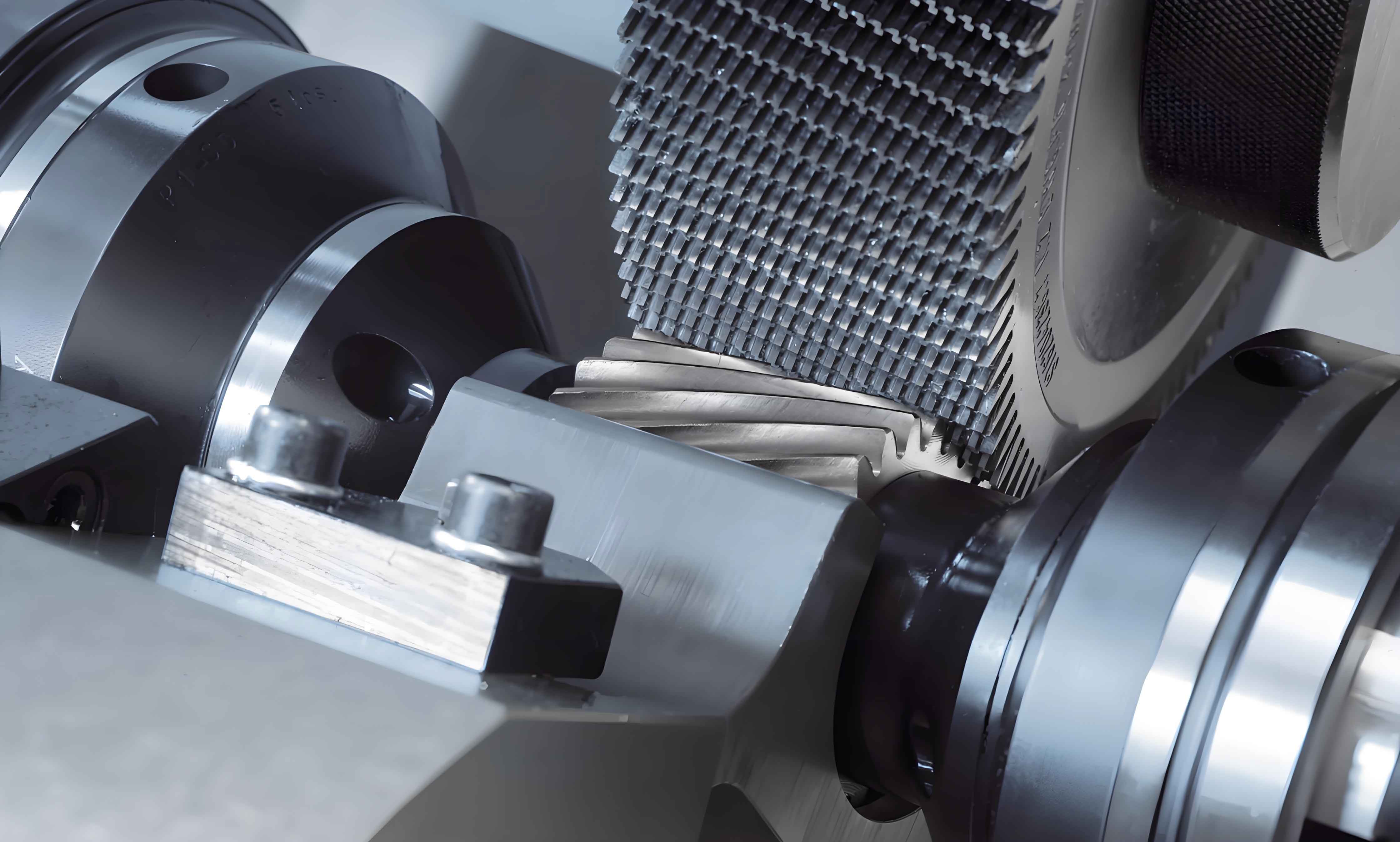
During the gear shaving operation, the cutter is driven to rotate. Through the meshing action, it imparts a rotational motion to the freely mounted workpiece. The relative motion between the two gears can be analyzed by examining the velocity vector $V_{c}$ at the pitch point on the cutter. This velocity can be resolved into two key components relative to the workpiece axis:
- Normal Component ($V_n$): This component is perpendicular to the workpiece axis and is responsible for driving the workpiece’s rotation. It defines the primary rolling motion of the mesh. $$ V_n = V_c \cdot \cos(\Sigma) $$
- Tangential/Axial Component ($V_a$): This component is parallel to the workpiece axis and is the source of the sliding action essential for cutting. It causes the cutter teeth to slide along the workpiece tooth flanks. $$ V_a = V_c \cdot \sin(\Sigma) $$
Simultaneously, a radial infeed force is applied, pressing the cutter and workpiece together. This force, combined with the sliding velocity $V_a$, enables the small cutting edges on the cutter to skim off a thin layer of material (typically 0.01-0.03 mm) from the workpiece tooth flanks. The contact point between the two gears moves along an “contact band” from the root to the tip of the tooth, and the longitudinal traverse of the workpiece or cutter ensures the entire face width is finished. This unique kinematic action allows gear shaving to effectively correct localized deviations in tooth profile and lead.
A Systematic Analysis of Errors in Gear Shaving
Despite its corrective capabilities, the gear shaving process is susceptible to various errors that can degrade the final gear quality. These errors can be categorized based on their origin: those stemming from the pre-shaved gear condition, those inherent to the shaving cutter, those induced by the shaving machine and setup, and those arising from the process dynamics itself.
1. Errors Originating from the Pre-Shaved (Hobbed/Shaped) Gear
Gear shaving is a “free-cutting” process with no rigid mechanical linkage between the cutter and workpiece spindles. Consequently, it has limited ability to correct certain long-period or systematic errors from the previous operation.
- Profile Form Error & Base Pitch Deviation ($f_f$, $f_{pb}$): While gear shaving can smooth out high-frequency profile irregularities, its ability to correct a systematically incorrect profile (e.g., caused by a misshapen hob) is constrained by the inherent accuracy of the cutter profile itself.
- Runout (Radial Error, $F_r$): The process can only partially compensate for gear runout. A significant portion of the radial eccentricity ($e_{geo}$) from the roughing operation is transformed into a post-shaving tangential error, manifesting as increased Total Profile Variation or Index Variation.
- Helical/Lead Error ($F_\beta$): Axial misalignment of the gear during hobbing/shaping results in a lead error. Gear shaving can correct this if the machine setup accurately opposes the error direction.
2. Errors Induced by the Shaving Cutter
The cutter is the primary tool in gear shaving, and its condition directly imprints on the workpiece.
| Error Source | Effect on Workpiece | Primary Cause |
|---|---|---|
| Cutter Tooth Profile Error | Direct replication onto gear profile ($f_f$), Base pitch deviation ($f_{pb}$) | Manufacturing inaccuracy, improper re-sharpening, wear. |
| Cutter Base Pitch Error | Workpiece base pitch deviation ($f_{pb}$) | Pitch accumulation errors during cutter manufacture. |
| Poor Cutter Surface Finish | High surface roughness ($Ra$) on gear teeth, “tearing” or “burnishing.” | Insufficient final polishing, coating failure, abrasive wear. The cutter Ra must be < 0.2 µm. |
| Excessive Cutter Wear/Outer Diameter Reduction | Insufficient active profile length on workpiece, tip/root interference in mesh. | Over-grinding during re-sharpening, lack of proper stock allowance on pre-shaved gear. |
3. Errors from Machine, Setup, and Process Dynamics
This category encompasses the most common and controllable variables in the gear shaving process.
| Error Category | Specific Error | Gear Error Manifestation |
|---|---|---|
| Machine & Setup Geometry | Incorrect crossed-axes angle ($\Sigma$) | Helical/Lead error ($F_\beta$), improper contact pattern. |
| Misalignment between machine centers and slide ways | Progressive lead error (taper) across face width. | |
| Workpiece arbor/collate runout | Increased radial runout ($F_r$) and index variation. | |
| Insufficient stock allowance or improper pre-shaved gear geometry | Poor correction, over-cutting at tip/root, excessive cutter load. | |
| Process Dynamics & Stability | Machine slide “stick-slip” or loose gibs | Irregular, non-periodic lead error patterns. |
| Excessive radial force or feed rate | Tooth deflection, altered profile, chatter marks, poor surface finish. | |
| Workpiece material hardness variation (too low: <170 HB; too high: >250 HB) | Low: Tearing, burrs. High: Rapid cutter wear, burnished surfaces, glazing. |
The interaction of these errors determines the final gear quality. For instance, the cumulative effect of profile error, lead error, and base pitch deviation directly dictates the contact pattern under load, which is critical for noise and durability.
Error Compensation and the Synthesis of Residual Errors
The most fascinating aspect of gear shaving is its potential for error compensation, particularly regarding the conversion and partial cancellation of eccentricity errors. To understand this, we must analyze the errors in terms of their effect on the line of action, which is the fundamental path of force transmission between meshing gears.
Errors from the roughing process can be decomposed into two primary types of eccentricity: Geometric Eccentricity ($e_{geo}$) and Kinematic (Motion) Eccentricity ($e_{kin}$).
- Geometric Eccentricity ($e_{geo}$): Caused by misalignment of the gear blank axis and the machining axis (e.g., chucking error). It produces a once-per-revolution radial runout ($F_r$).
- Kinematic Eccentricity ($e_{kin}$): Caused by inaccuracies in the machine tool’s indexing or worm drive (e.g., worm wheel eccentricity). It produces a once-per-revolution angular error.
Both eccentricities project an error $\Delta T$ onto the line of action. The key insight is that their projections are vector quantities with specific directions (left flank vs. right flank) and can be decomposed into radial and tangential components relative to the gear’s rotation. During gear shaving, the process behaves differently towards these components.
Let’s consider the geometric eccentricity $e_{geo}$ at an angular position $\phi$ on the gear. Its projection on the line of action for a pressure angle $\alpha$ is:
$$ \Delta T_{geo} = e_{geo} \cdot \sin(\alpha \pm \phi) $$
(Using $+$ for left flank, $-$ for right flank).
This can be decomposed into a radial component ($\Delta T_{geo}^{rad}$) and a tangential component ($\Delta T_{geo}^{tan}$) relative to the workpiece’s theoretical rotation:
$$ \Delta T_{geo}^{rad} = e_{geo} \cdot \cos\alpha \cdot \sin\phi $$
$$ \Delta T_{geo}^{tan} = \pm e_{geo} \cdot \sin\alpha \cdot \cos\phi $$
The nature of gear shaving is such that the radial error component manifests as equal-magnitude, equal-direction deviations on simultaneously contacting left and right flanks. This component is effectively “seen” and removed by the cutter. However, the tangential error component manifests as equal-magnitude but opposite-direction deviations on simultaneously contacting flanks. The free-cutting, self-centering action of the gear shaving process cannot distinguish this as an error to be removed; it simply adapts to it. Therefore, the post-shaving residual line-of-action error due to $e_{geo}$ is primarily the tangential component:
$$ \Delta T_{shaved}^{geo} \approx \pm e_{geo} \cdot \sin\alpha \cdot \cos\phi $$
Now, consider the kinematic eccentricity $e_{kin}$ from the roughing machine, which has a fixed phase relationship $\psi$ relative to the gear. Its line-of-action error is:
$$ \Delta T_{kin} = e_{kin} \cdot \sin(\alpha \pm (\phi + \psi)) $$
During gear shaving, this error, being a function of the gear’s angular position, is largely retained because the shaving process does not have an independent reference to correct it; it follows the existing index.
The total post-shaving error $\Delta T_{total}$ is the sum of the residual geometric error and the largely uncorrected kinematic error:
$$ \Delta T_{total}^{left} = e_{geo} \cdot \sin\alpha \cdot \cos\phi + e_{kin} \cdot \sin(\alpha + \phi + \psi) $$
$$ \Delta T_{total}^{right} = -e_{geo} \cdot \sin\alpha \cdot \cos\phi + e_{kin} \cdot \sin(\alpha – \phi – \psi) $$
This reveals the compensation mechanism. The first term from $e_{geo}$ and parts of the second term from $e_{kin}$ can have opposite signs. By carefully controlling the magnitude and phase ($\phi$) of the residual geometric eccentricity during the shaving setup (e.g., through deliberate axial misalignment of the gear on its arbor), it is possible to offset the effect of the kinematic eccentricity. The optimal compensation condition, where the post-shaving error is minimized, is achieved when the following relationship is satisfied:
$$ e_{geo} \cdot \sin\alpha \cdot \cos\phi \approx – e_{kin} \cdot \sin\alpha \cdot \cos(\phi + \psi) $$
This simplifies to a condition relating the phases and magnitudes:
$$ e_{geo} \cdot \cos\phi \approx – e_{kin} \cdot \cos(\phi + \psi) $$
When this condition is met through precise process design and setup, gear shaving transitions from a mere finishing operation to a powerful error-synthesis and compensation technique, yielding gears with superior functional accuracy even when preceding operations were not perfect.
Advanced Strategies for Maximizing Gear Shaving Precision
Building on the fundamental understanding of errors and compensation, modern gear shaving employs several advanced strategies:
- CNC-Controlled Shaving: Modern CNC gear shaving machines allow for programmable modification of the cutter path. This enables:
- Crowning and Lead Modification: Deliberate introduction of a slight barrel shape (crowning) or end relief on the tooth flank to compensate for anticipated deflection under load, improving contact patterns. The crown amount $C$ can be precisely controlled. $$ z(x) = C \cdot \left(1 – \frac{(2x)^2}{F_w^2}\right) $$ where $x$ is the position along the face width $F_w$, and $z$ is the relief.
- Targeted Error Correction: Using in-process or post-process measurement feedback, the CNC can adjust the shaving path in subsequent cycles to correct systematic errors specific to a batch of gears.
- Process Monitoring and Adaptive Control: Monitoring cutting forces, acoustic emissions, or motor current can detect anomalies like tool wear, chatter onset, or material hardness variations, allowing for real-time adjustment of feed rates.
- Optimized Cutter Design & Coating: Using coated cutters (TiN, TiCN, TiAlN) significantly increases tool life and maintains a sharp cutting edge, directly improving surface finish and profile consistency. The design of the gullet (chip space) and rake angle is critical for efficient chip evacuation and stable cutting.
- Integrated Pre-Shave Geometry: The design of the pre-shave (hobbed/shaped) gear tooth is crucial. It must have a defined stock allowance distribution, often with protuberance or tip/root relief, to ensure the shaving cutter engages correctly and does not over-cut at the tip or under-cut at the root.
In conclusion, gear shaving is a sophisticated precision finishing process whose effectiveness hinges on a delicate balance between its inherent corrective actions and its susceptibility to specific errors. By thoroughly understanding the kinematics of the crossed-axes mesh, systematically categorizing the sources of error from the workpiece, cutter, machine, and process, and leveraging the mathematical principles of error vector synthesis and compensation, one can transform gear shaving from a simple stock removal operation into a powerful technique for achieving high-quality gear geometries. The ongoing integration of CNC technology, advanced cutter materials, and process analytics continues to push the boundaries of what is possible with this efficient and versatile gear finishing method.