
The escalating global focus on energy efficiency and emission reduction has placed significant pressure on the automotive industry to innovate. Vehicle weight reduction stands as a primary strategy, with studies indicating that a 10% reduction in vehicle mass can lead to a 6-8% improvement in fuel economy. Among various components, the rear axle reducer represents a substantial mass contributor. Optimizing its core power-transmitting element—the spiral bevel gear pair—offers a direct path to weight savings not only for the gears themselves but also for associated components like bearing housings and the axle casing due to reduced load dimensions.
Traditional symmetric spiral bevel gear designs utilize identical pressure angles on both the drive (convex) and coast (concave) sides of the tooth. While increasing the pressure angle is a well-known method for enhancing contact and bending strength, applying a larger angle to both sides of a standard tooth profile leads to an undesirably sharp tooth tip, compromising its integrity. Recognizing that automotive axles predominantly operate in the forward drive direction, we propose an innovative asymmetric design: a spiral bevel gear employing a larger pressure angle on the working drive side and a standard pressure angle on the non-working coast side. This double pressure angle configuration harnesses the strength benefits of a high pressure angle where it is most needed while avoiding the pitfalls of a pointed tooth top. Crucially, this allows for a reduction in module size while maintaining or even improving load capacity, directly enabling a more compact and lighter gear set. This paper details the complete process from the mathematical modeling and finite element analysis of such a gear to its specialized manufacturing and final experimental validation.
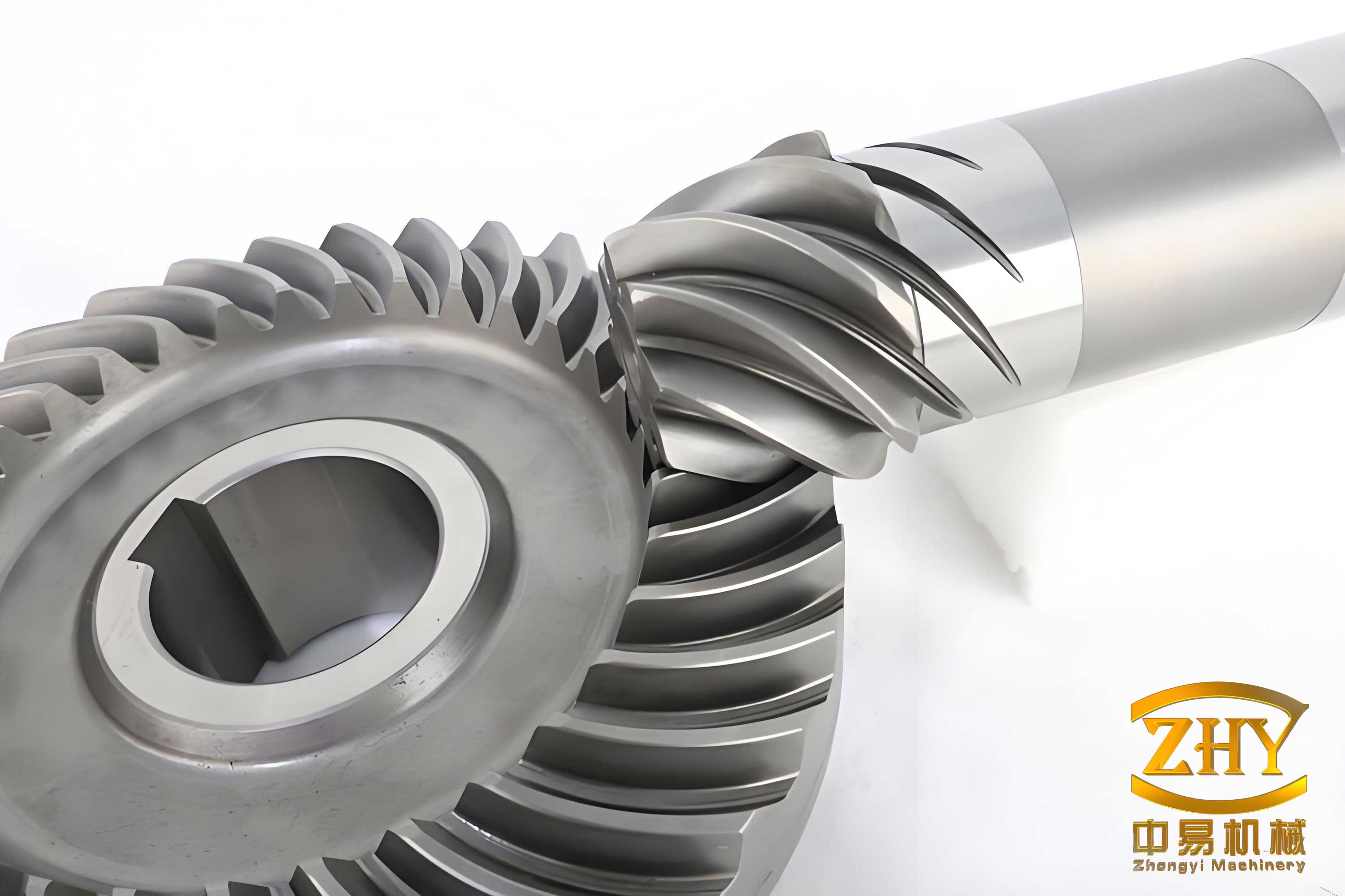
The geometry of a spiral bevel gear is inherently complex, defined in a spherical coordinate system. For a double pressure angle spiral bevel gear, the tooth profiles on the drive and coast sides originate from different base cones due to their distinct pressure angles. The spherical involute for the drive-side (large pressure angle, \(\alpha_d\)) tooth profile at the outer end is derived as follows:
$$ \rho = R $$
$$ \theta = \arccos[\cos\delta_f / \cos(\delta_f \cdot \sin\phi_d)] $$
$$ \phi = \arccos[\tan\delta_{bd} / \tan\theta] – \pi/2 – \delta’ + \phi_d $$
where \(R\) is the outer cone distance, \(\delta_f\) is the root angle, \(\delta’\) is the pitch angle, \(\phi_d\) is the drive-side offset angle at the pitch circle, and \(\delta_{bd}\) is the drive-side base cone angle. The base cone angle is calculated from the designed pressure angle:
$$ \delta’_{bd} = \arctan[(1 – k) \cdot \tan\delta’ \cdot \cos\alpha_d] $$
$$ \delta_{bd} = \arccos\left[\frac{\cos\delta’_{bd}}{\cos\phi_d}\right] = \arccos\left[\frac{1}{\cos\phi_d \cdot \sqrt{1 + (1-k)^2 \cdot \tan^2\delta’ \cdot \cos^2\alpha_d}}\right] $$
Here, \(k\) is the spiral bevel gear ratio factor. Similarly, the coast-side (standard pressure angle, \(\alpha_c\)) profile at the outer end is given by:
$$ \rho = R $$
$$ \theta = \arccos[\cos\delta_f / \cos(\delta_f \cdot \sin\phi_c)] $$
$$ \phi = \arccos[\tan\delta_{bc} / \tan\theta] – \pi/2 + \delta’ – \phi_c $$
with \(\phi_c\) as the coast-side offset angle and \(\delta_{bc}\) as the coast-side base cone angle:
$$ \delta’_{bc} = \arctan[(1 – k) \cdot \tan\delta’ \cdot \cos\alpha_c] $$
$$ \delta_{bc} = \arccos\left[\frac{\cos\delta’_{bc}}{\cos\phi_c}\right] $$
The tooth lengthwise direction is defined by the circular arc traced by the cutter head. In spherical coordinates, the fillet line equation is:
$$ \rho = r_0 / \sin j $$
$$ \theta = \delta’ $$
$$ \phi = \phi_p – (S – j)/\sin\delta’ $$
where \(r_0\) is the cutter radius, and angles \(S\) and \(j\) are determined by the machine-tool settings and gear blank geometry. The corresponding profiles at the inner end of the tooth are obtained by substituting \(\rho = R – B\) (where \(B\) is face width) and accounting for the phase shift due to the fillet line curvature from the outer to inner end.
Using these derived equations, a parametric three-dimensional model of the double pressure angle spiral bevel gear pair was developed in a CAD environment. For a concrete case study, the design parameters from a SUV rear axle reducer were adopted. Three gear sets were modeled for comparison: the proposed lightweight set with a module \(m=4.0\) mm and double pressure angles (30°/20°), a conventional symmetric set with \(m=4.0\) mm and 20° pressure angles, and the original symmetric set with \(m=4.5\) mm and 20° pressure angles. The key parameters are summarized below:
| Parameter | Double Pressure Angle Gear (m=4.0) | Symmetric Gear 1 (m=4.0) | Symmetric Gear 2 (m=4.5) |
|---|---|---|---|
| Module, m (mm) | 4.0 | 4.0 | 4.5 |
| Number of Teeth, z1/z2 | 19 / 28 | 19 / 28 | 19 / 28 |
| Spiral Angle, β | 35° (LH) | 35° (LH) | 35° (LH) |
| Working Side | Pinion Concave, Gear Convex | Pinion Concave, Gear Convex | Pinion Concave, Gear Convex |
| Pressure Angle, α (°) | 30 (Drive) / 20 (Coast) | 20 | 20 |
| Profile Shift Coefficient, x | -0.21 | -0.21 | -0.21 |
The most common failure mode for spiral bevel gears in axle applications is contact fatigue (pitting). Therefore, a precise evaluation of the contact stress is paramount. A finite element analysis (FEA) using the elastic contact method was performed. The CAD models were imported into FEA software, and a three-tooth segment model was constructed to capture accurate load sharing and boundary conditions. SOLID95 second-order elements were used, with heavy mesh refinement in the potential contact zones. Surface-to-surface contact elements (CONTA174) and target elements (TARGE170) were defined between the pinion concave and gear convex surfaces. Boundary conditions simulated the actual mounting: the gear’s bore was fully constrained, while the pinion’s bore was fixed in radial and axial directions in a cylindrical coordinate system, with the driving torque of 619 N·m applied as a force-couple on its inner surface nodes.
The FEA results for contact stress are critical. The contour plots revealed the characteristic elliptical contact pattern on the tooth flanks for all gear sets. The maximum contact stress values extracted from the analyses are presented below:
| Gear Set | Max Contact Stress – Pinion (MPa) | Max Contact Stress – Gear (MPa) |
|---|---|---|
| Double Pressure Angle (m=4.0) | 409 | 410 |
| Symmetric Gear 1 (m=4.0) | 441 | 459 |
| Symmetric Gear 2 (m=4.5) | 424 | 417 |
The results demonstrate a clear advantage for the double pressure angle spiral bevel gear. Compared to the symmetric gear of the same module (4.0 mm), the maximum contact stress is reduced by approximately 12%. More importantly, the contact stress in the lightweight (m=4.0) double pressure angle design is lower than that in the larger, heavier original (m=4.5) symmetric gear. This confirms the fundamental premise: the double pressure angle design enhances contact strength, permitting a reduction in module and consequent weight savings without compromising, and even improving, load capacity.
The unique tooth geometry of the double pressure angle spiral bevel gear necessitates specialized cutting tools and processes. Standard symmetric gear cutters cannot produce the asymmetric profiles. The machining involves both dual-blade (for roughing and finishing one side of the gear) and single-blade (for finishing the other side) cutter heads. For the gear (driven member), where the convex side is the working (30°) surface, the pressure angles on the cutter blades must be corrected for the cutter tilt relative to the root line. The working-side pressure angles for the inside and outside blades (\(\alpha_{inc}\), \(\alpha_{ouc}\)) are calculated as:
$$ \Delta\alpha_2 = \theta_{f2} \cdot \sin\beta $$
$$ \alpha_{inc} = \alpha_d + \Delta\alpha_2 $$
$$ \alpha_{ouc} = \alpha_c – \Delta\alpha_2 $$
where \(\theta_{f2}\) is the gear root angle. Conversely, for the pinion, where the concave side is the working surface, the corresponding cutter blade pressure angles are:
$$ \alpha_{ind} = \alpha_c + \Delta\alpha_2 $$
$$ \alpha_{oud} = \alpha_d – \Delta\alpha_2 $$
Based on these calculations, custom inside and outside blade cutters were designed and manufactured. A five-machine, five-cutter process utilizing the fixed-setting method was employed. The gear was finished in one operation with a dual-blade head, while the pinion required separate inner and outer single-blade finishing operations after roughing. This process allows for independent control over the contact patterns on the convex and concave flanks. The physical gears were successfully produced. The weight comparison was striking: the double pressure angle gear showed a 37% reduction in mass for the driven gear and a 10% reduction for the pinion (which includes a integral shaft), resulting in an overall weight reduction of approximately 25% for the gear pair.
To validate the analytical predictions and the real-world performance of the lightweight design, a full-scale fatigue endurance test was conducted on a mechanical dual-loop closed-circuit test rig. The test parameters replicated the severe operating conditions of the original SUV axle, with an input torque of 619 N·m at 200 rpm. The testing procedure and evaluation strictly followed industry standards (e.g., QC/T 533-1999). The acceptance criteria require a minimum life of 300,000 cycles and a median life of 500,000 cycles for the test samples.
The test results provided conclusive validation:
| Gear Set | Standard Requirement (Cycles) | Test Result (Cycles) | ||
|---|---|---|---|---|
| Minimum | Median | Minimum | Median | |
| Double Pressure Angle (m=4.0) | ≥ 300,000 | ≥ 500,000 | > 313,000 | > 617,000 |
| Original Symmetric (m=4.5) | ≥ 300,000 | ≥ 500,000 | > 302,000 | ~612,000* |
*Test stopped due to severe pitting and increased noise.
The double pressure angle spiral bevel gear pair not only met but exceeded the standard requirements. Its median fatigue life surpassed that of the original, heavier symmetric gear pair. Post-test inspection of the double pressure angle gears revealed no signs of tooth breakage, crushing, or severe pitting, confirming their superior contact fatigue resistance. This experimental outcome aligns perfectly with the finite element analysis, which predicted lower contact stress for the new design.
In conclusion, this work establishes a comprehensive framework for the lightweight design of spiral bevel gears through pressure angle asymmetry. The derivation of the spherical coordinate tooth geometry provides the foundation for modeling. Finite element contact stress analysis quantitatively demonstrated that a double pressure angle configuration (30°/20°) with a reduced module (4.0 mm) generates lower contact stress than a standard symmetric design with a larger module (4.5 mm). The specialized cutter design and manufacturing process successfully translated the theoretical model into physical components, achieving a 25% weight reduction for the gear pair. Finally, rigorous closed-loop fatigue testing validated the design, proving that the lightweight double pressure angle spiral bevel gear offers enhanced durability compared to the conventional heavier design. This methodology presents a viable and effective technological pathway for weight reduction in vehicle transmission systems, contributing directly to improved fuel efficiency and reduced emissions.