
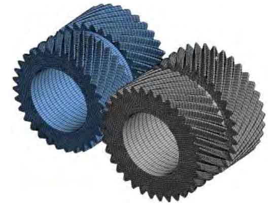
In order to verify the accuracy of the load contact analysis model of herringbone gear with centering error, a three-dimensional model of herringbone gear pair with centering error is established. According to the requirements of machining herringbone gear, the centering error is required to be controlled within grade 6 accuracy. In order to facilitate quantitative analysis, the pinion in this paper does not contain centering error, and the large gear contains centering error. Therefore, when the three-dimensional solid modeling is carried out with the main parameters shown, the median error value is 0.02 mm, that is, the helical gear at the left end of the big wheel rotates by 0.01 °. The established geometric model is imported into ANSYS to establish the finite element model. The element type of the mesh model adopts eight node hexahedron element, which is meshed by structured technology. The number of partition nodes is 400 480 and the number of cells is 134 864, as shown in Figure 1.
The corresponding boundary conditions are set in the finite element software, and the rotating pair is set in the axis of the big wheel, only the degree of freedom of rotation along the axis is retained; A cylindrical pair is arranged on the small wheel to ensure the freedom of the small wheel to rotate and move axially. In order to prevent the simulation from converging due to the sudden change of speed and load, gradually apply speed and torque within 0 ~ 0.1 s to gradually accelerate the system from static state to rated speed state. The comparison of axial displacement and bearing transmission error of herringbone gear obtained by finite element analysis is shown in Figure 2.
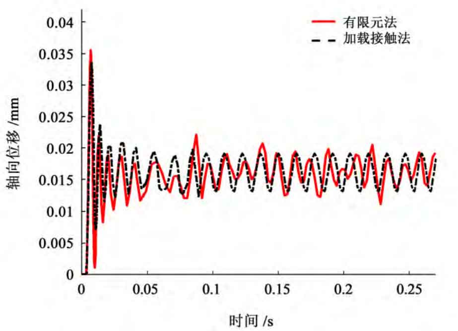
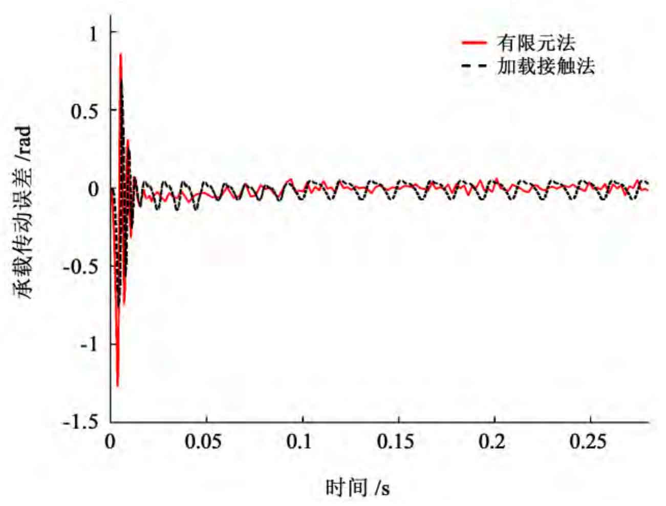
Through comparison, it can be seen that the finite element analysis results are basically consistent with the loading contact analysis results. Because the influence of gear contact nonlinearity and friction nonlinearity is considered in the finite element method, the calculation results fluctuate obviously. In addition, the logarithm of teeth changes alternately in the meshing process of herringbone gear pair, which makes the axial displacement and dynamic transmission error of herringbone gear pair change periodically. At the beginning of the meshing movement of the gear pair, the clearance between the left and right tooth surfaces of the herringbone gear pair is different due to the existence of alignment error. One end contacts and collides first, resulting in a sudden change in the meshing stiffness of the gear, the gear moves to the other end, the axial displacement increases abruptly, and the transmission error also changes abruptly. With the increase of speed and load, the axial displacement is 0.018 mm, The dynamic transmission error fluctuates up and down at -0.174 rad. In addition, the instantaneous left-right imbalance caused by the instability of tooth shape and other factors in the transmission process of gear pair will also aggravate the sudden change of gear axial displacement, which is consistent with the vibration impact caused by gear meshing in and out under actual conditions.