Abstract
This paper delves into the intricate mechanisms influencing the lubrication effectiveness of cylindrical gears with variable hyperbolic circular-arc-tooth traces (VH-CATT) under oil injection lubrication, particularly focusing on the complex airflow behaviors induced by their unique tooth profile. Utilizing computational fluid dynamics (CFD), the study models and simplifies the fluid domain, analyzes the interference between high-speed airflow and oil injection jets, and identifies the optimal oil injection angle through streamline maps. By examining oil distribution, average oil volume fraction on the tooth surface, and oil pressure, the study reveals the impact of various oil injection parameters on tooth surface lubrication. The results indicate that by orienting the oil injection angle 10.73° towards the driving gear, along with appropriately increasing the injection speed, reducing the injection distance, and lowering the gear rotational speed, the lubrication effectiveness of the gear transmission can be enhanced. This research provides a theoretical foundation for the design and parameter optimization of oil injection lubrication and cooling systems for this type of gear transmission.

Keywords: Cylindrical Gear with Variable Hyperbolic Circular-arc-tooth Trace; Computational Fluid Dynamics (CFD); Oil Injection Lubrication; Average Oil Volume Fraction of Tooth Surface
1. Introduction
Cylindrical gears, especially those with VH-CATT profiles, are gaining industry attention due to their high load capacity, excellent meshing performance, and absence of axial forces. However, the unique tooth surface structure significantly impacts airflow behavior, further influencing lubrication effectiveness. Therefore, studying the airflow behavior and oil injection lubrication mechanism under the influence of VH-CATT cylindrical gear’s unique tooth profile is crucial.
2. Literature Review
Extensive research has been conducted on gear lubrication theory and numerical calculations, yielding fruitful results. Studies by Akin et al. explored the impact of different gear mesh states and parameters on lubrication efficiency, while Wang et al. analyzed the pressure and airflow fields around high-speed rotating gears, demonstrating the air barrier effect that hinders oil entry into the meshing area. Dai et al. and Zhu et al. utilized CFD to study nozzle flow characteristics and calculate precise impact depths of bevel gears under oil injection lubrication, respectively.
3. Mathematical Model and Simulation Setup
3.1 VH-CATT Cylindrical Gear Mathematical Model
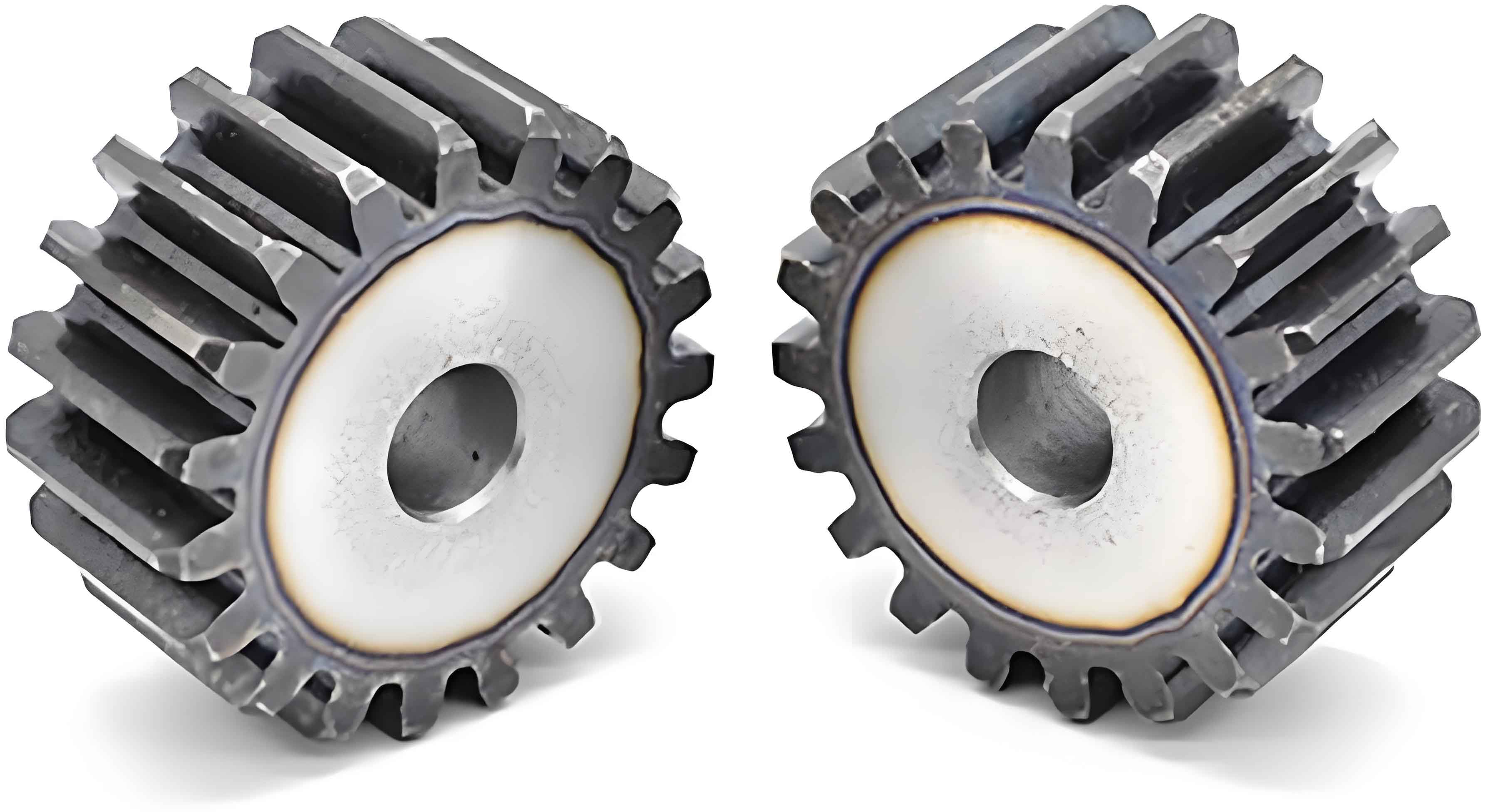
The tooth surface of a VH-CATT cylindrical gear is characterized by a circular-arc tooth trace and an involute mid-section profile, with other cross-sections parallel to the mid-section being envelopes of varying hyperbola families.
Table 1: Geometrical and Operating Parameters of VH-CATT Cylindrical Gear Unit
| Parameter | Pinion | Gear |
|---|---|---|
| Number of teeth | 21 | 43 |
| Module (m) /mm | 4 | 4 |
| Pressure angle (α0) /(°) | 20 | 20 |
| Rotational speed (n1, n2) /(r·min-1) | 6000 | (Calculated based on gear ratio) |
| Center distance (l) /mm | 100 | – |
| Tooth width (B1) /mm | 40 | – |
| Nozzle diameter (D) /mm | 5 | – |
| Lubricant density (ρ) /(kg·m-3) | 960 | – |
| Injection height (d) /mm | Varies | – |
| Injection speed (v) /(m·s-1) | Varies | – |
3.2 CFD Model Setup
The study uses the Eulerian multiphase flow model (VOF) to simulate the oil injection process, revealing the influence of different injection heights, speeds, and gear speeds on tooth surface lubrication. The geometric model focuses on the mesh-in side oil injection of VH-CATT cylindrical gears.
4. Results and Discussion
4.1 Influence of Unidirectional Flow on Lubrication Effectiveness
Streamline maps show a layered airflow phenomenon around the gear teeth, with an air barrier formed at high speeds. Oil injection jets penetrate this barrier to lubricate the meshing area, but interference with high-speed airflow reduces oil flow into the meshing area, lowering lubrication efficiency.
4.2 Optimal Oil Injection Angle
The study identifies a trajectory with minimal airflow impact, with an angle of 10.73° relative to the pitch line, as the optimal oil injection direction for maximum lubrication efficiency.
4.3 Effect of Oil Injection Speed
Higher oil injection speeds more effectively deliver oil to the tooth meshing area, with oil concentrating below the nozzle, favorable for VH-CATT cylindrical gear lubrication.
Table 2: Oil Pressure Statistics in the Meshing Zone at Different Injection Speeds
| Injection Speed (v) /(m/s) | Positive Pressure | Negative Pressure (Absolute) | Pressure Difference |
|---|---|---|---|
| 30 | – | – | – |
| 40 | – | – | – |
| 50 | – | – | – |
| 60 | Highest | Highest | Highest |
| 70 | – | – | – |
| 80 | – | – | – |
4.4 Effect of Injection Height
At shorter injection distances, oil on the VH-CATT cylindrical gear tooth surface is more concentrated due to lesser airflow impact. As distance increases, oil diffusion and reduced jet velocity lead to broader oil spread on the tooth surface.
4.5 Effect of Gear Rotational Speed
Increasing gear speeds cause greater airflow momentum around the gears, disrupting the oil injection jet and reducing the average oil volume fraction near the meshing area.
5. Conclusion
The study concludes that for optimal lubrication of VH-CATT cylindrical gears under oil injection:
- The oil injection angle should be set to 10.73° towards the driving gear.
- Increasing oil injection speed (up to 60 m/s) enhances oil entry into the meshing area.
- Shorter injection distances (less than 40 mm) result in higher oil content and pressure in the meshing area.
- Lowering gear speeds increases oil content in the meshing area.
These findings provide insights for designing and optimizing oil injection lubrication and cooling systems for VH-CATT cylindrical gears.
