In the available literature, the manufacturing technology of ball gear pair explored can be summarized as casting molding, forming processing and generation processing.
1. Casting molding
Iron mold sand coated casting technology is the earliest processing method for processing involute ring gear ball gear. The tooling equipment used in iron mold sand coating casting technology includes sand shooting head, sand coating layer, iron mold and molding plate, as shown in Figure 1.
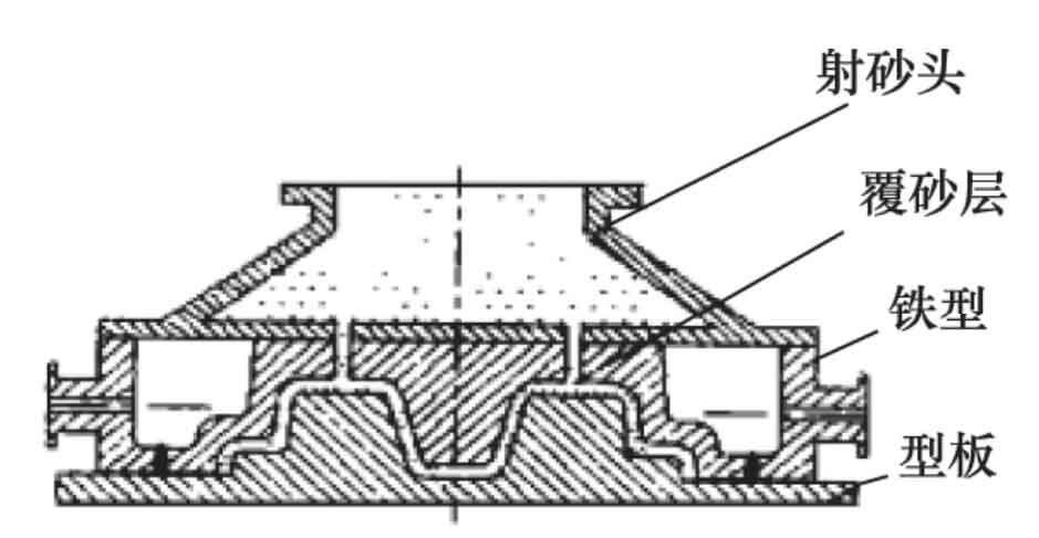
In the iron mold sand coated casting process, it is preferred to close the iron mold and the model, inject the sand into the molding sand from the sand shooting hole, form an iron mold sand coated casting mold similar to the shape of involute ring gear ball gear after curing, then cover a layer of film coated sand with a certain thickness on the near shaped iron mold, and finally inject molten iron into the coarse formed iron mold sand coated casting cavity to form a casting.
In 2008, Yang Junqiang and others put forward the machining method of austempered ductile iron gear casting made of sand coated iron profile, which can realize the high-precision machining of involute ring gear ball gear. The processed gear has high precision, low hardness, good compactness and high yield, and can effectively reduce gear meshing noise and improve gear service life. However, there are still some improvements in this method for the preservation of a large number of iron molds in the workshop and the general and special use of different castings. It can not guarantee the shrinkage cavity and other defects of castings in process design, and these aspects need to be improved.
2. Forming process
Forming method is a common method of involute gear machining. Pan cunyun proposes to use profiling turning or profiling milling to realize the tooth profile machining of involute ring gear ball gear, and the cutting edges of its turning tool or milling cutter are involute cutting edges. When using profiling turning or profiling milling to cut gear teeth, the workpiece rotates around the polar axis. The difference lies in whether the cutting tool rotates or not.
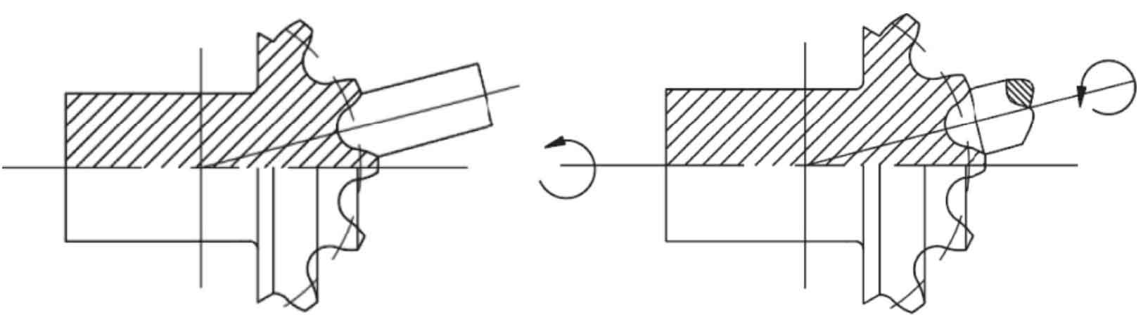
The profiling turning process is shown in Fig. 2A. When the workpiece polar axis rotates, the tool does not rotate all the time, and only does the feeding movement along the radial direction of the ball blank. After the workpiece rotates a certain angle around the polar axis, the turning tool cuts a ring gear and repeats the previous movement until the forming of involute ring gear is completed. Profiling milling is shown in Fig. 2B. The workpiece rotates around the polar axis. The milling cutter tool does the same feed movement along the radial direction of the ball blank as the turning method. At the same time, it also rotates around its own polar axis to realize the machining of involute ring gear. However, due to the limited number of cutters, profiling milling productivity is low and gear accuracy is low.
3. Generation processing
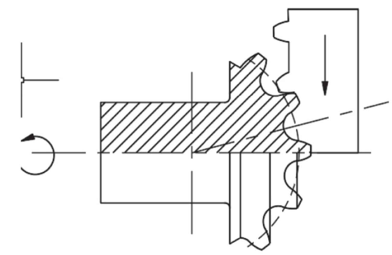
The generation method is an efficient machining method for involute gear cutting. Its simulation 1 carries out gear tooth cutting according to the envelope principle. Based on the evolution process of ball gear, pan cunyun puts forward the generation cutting of involute ring gear ball gear. Fig. 3 is the schematic diagram of generating machining and cutting of involute ring gear ball gear. During cutting, the gear blank workpiece and rack cutter make pure rolling motion together to form the involute tooth profile. At the same time, they make rotary motion around the polar axis and the cutter makes linear motion to form the involute ring surface.
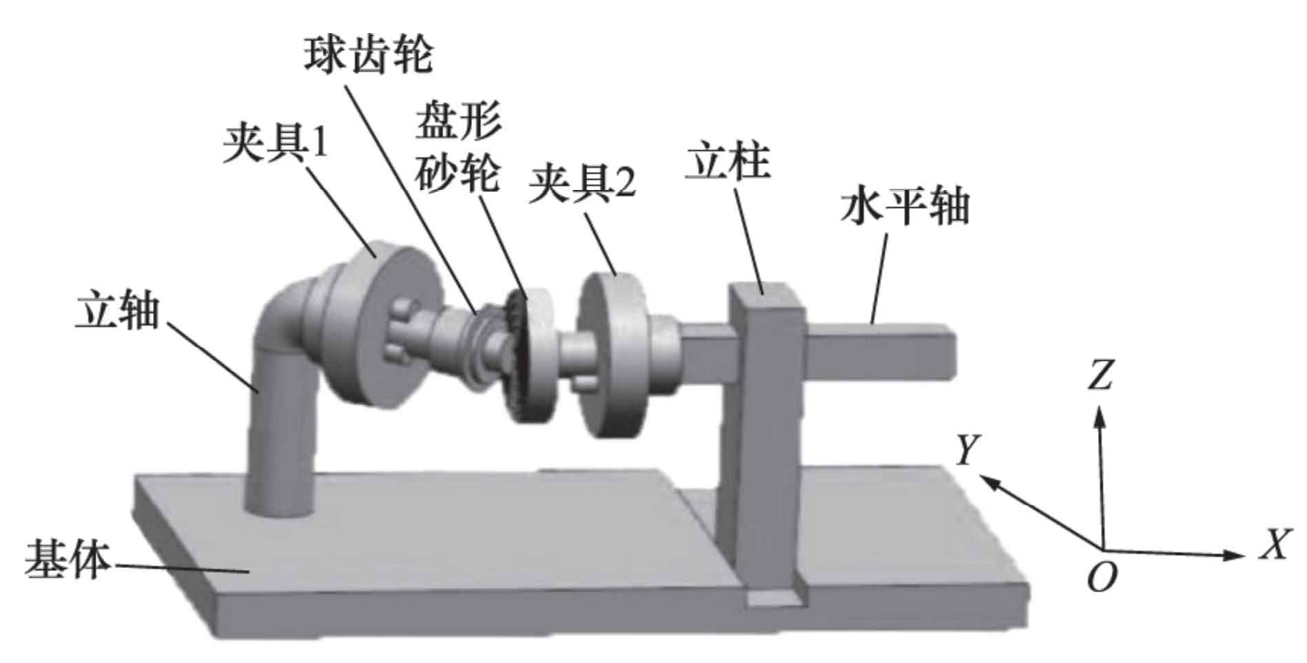
Referring to the principle of gear evolving into rack, Li Ting and others put forward the grinding method of ball gear profile generation method by using the ball gear disk mechanism as the theoretical basis, and designed the precision grinding equipment of disk grinding wheel based on the generation method, as shown in Fig. 4. The grinder is composed of matrix, vertical shaft, fixture 1, ball gear, gear disc, fixture 2, column and horizontal shaft, in which the gear disc, i.e. disc-shaped sand wheel, is used as grinding tool. The grinder has 5 degrees of freedom and can carry out 3 rotational movements and 2 translational movements. However, when the machine tool is processed for a long time, the rotation of the vertical shaft is easy to loosen, and the friction between the column and the horizontal shaft will cause great wear of the equipment, affecting the gear processing accuracy and processing efficiency.
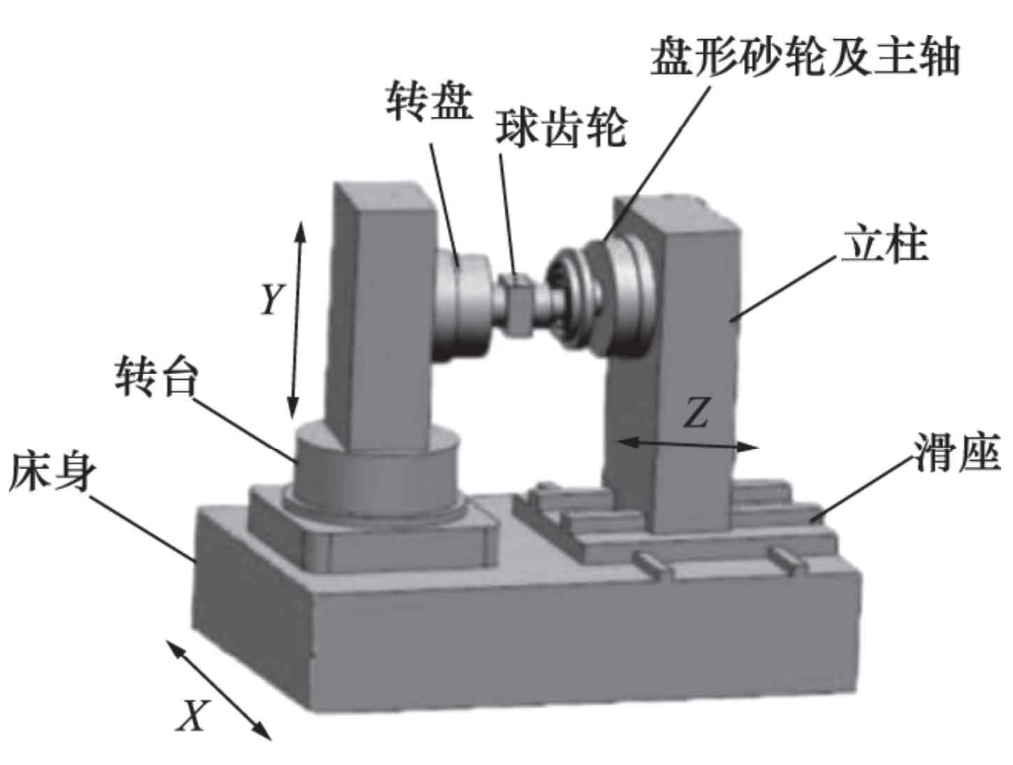
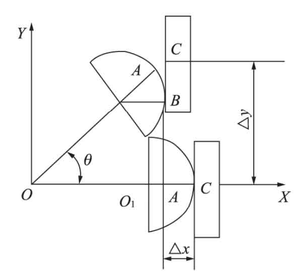
The improved model is shown in Figure 5. It replaces the 360 ° rotating column with the turntable, which improves the flexibility of column rotation; The horizontal axis is replaced by a sliding seat that can feed along the X and Y axes, which increases the stability of grinding and the durability of machine tools and equipment, and enhances the vibration resistance. When machining the gear, the ball gear does not rotate around its ball center, but swings with the turntable. Therefore, the disc grinding wheel should translate along the Z axis while translating along the X axis. The normalized kinematic chain relationship is shown in Fig. 6. The ball gear rotates around the swing center, and the tangent point between the disc grinding wheel and the ball gear changes from point C to point B. according to the fact that its contact arc length AB is equal to the segment CB on the indexing line of the disc grinding wheel, the displacement equations along the x-axis and y-axis are deduced, and its meshing principle is verified. Through practice, the machine tool can realize the finish machining of involute ring gear ball gear pair.
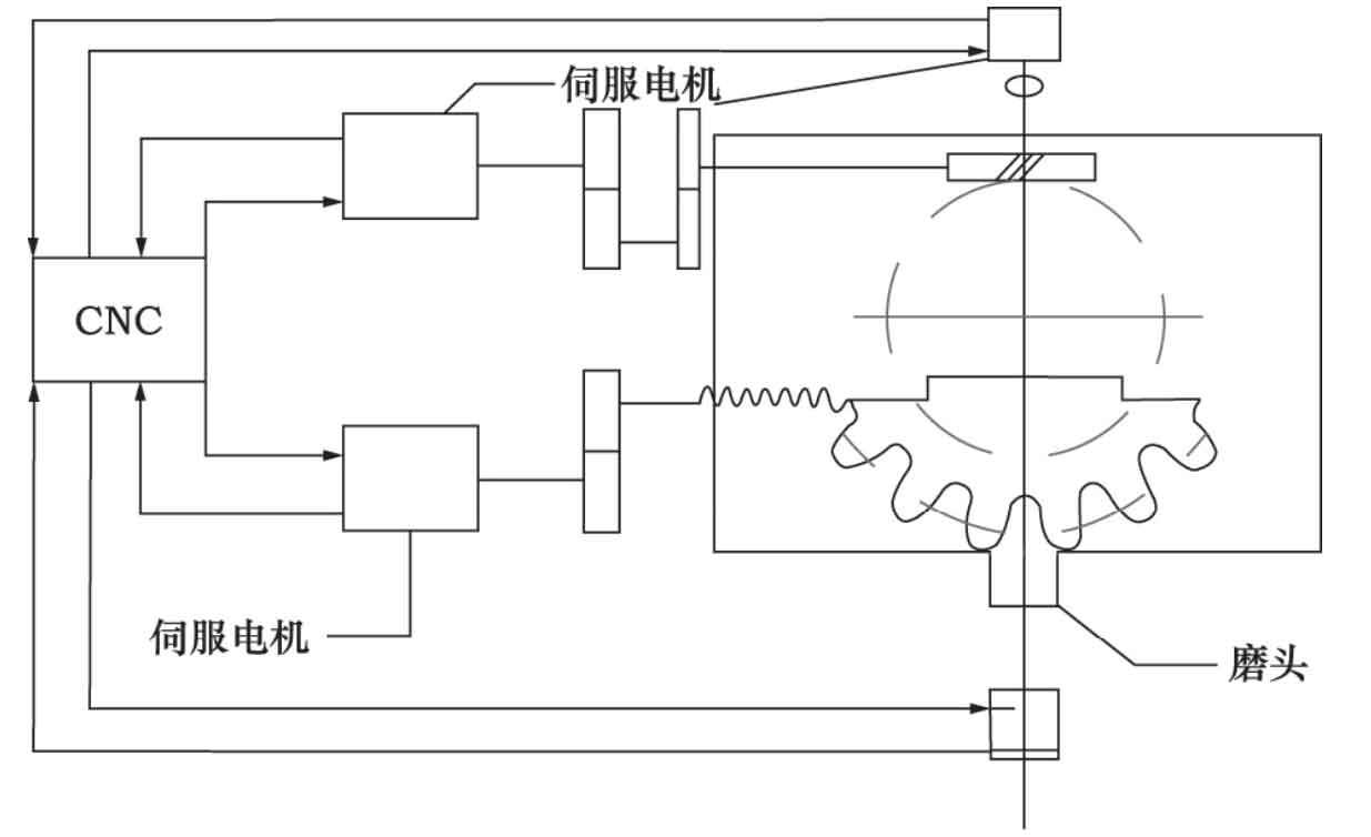
Li Gaofeng and pan cunyun designed the grinding device of ball gear by generating method based on the principle of generating method, as shown in Figure 7. The finger grinding head with a normal section of a single gear ring is used as the grinding tool. The finger grinding head is a high-speed electric grinding head, which is stable and can produce sufficient grinding speed when used, the diameter of the grinding tool is reduced, and the speed of the grinding tool is improved. CNC indexing motion is adopted, and the two servo motors are connected with CNC. CNC plays a leading control role. CNC controls the motion of grinding workpiece, indexing gear change, reciprocating smooth grinding and changing the rotating speed of workpiece motor, which improves the precision of ball gear grinding and shortens the machining cycle. The technical scheme overcomes the shortage of uneven processing quality caused by unstable rotating speed of abrasive tools, and has practical value.