The helical gear can be regarded as a sheet helical gear. The helical gear is divided into m sheet helical gears along the tooth width direction AA ‘, taking M = 30. Each sheet helical gear can be equivalent to a sheet spur gear. According to the theory of material mechanics, considering the bending deformation, shear deformation, radial compression deformation, Hertz contact deformation and wheel body deformation of the gear, the equivalent stiffness of each sheet along the meshing line at each meshing position of the helical gear can be obtained as follows:

Where kt1 and kt2 are the main and driven gear tooth stiffness, including bending stiffness KB, shear stiffness KS, radial compression stiffness Kr and wheel body deformation stiffness KF; KH is Hertz contact stiffness.


The equivalent stiffness of each slice is added to obtain the meshing stiffness of helical gear at each meshing position. The schematic diagram of helical gear slice model is shown in Figure 1.
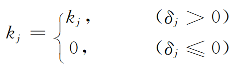
Side clearance: when the gear is not affected by the normal force FN, each pair of thin helical gear pairs along the meshing line of the helical gear should contact at the theoretical position; When the gear is subjected to the normal force FN, the deformation of each thin helical gear pair along the normal gear Δ j = δ Is equal, δ Is the transmission error when the helical gear pair is subjected to the normal force FN, and j is the number of each thin helical gear pair (J ≤ 1,…, m), as shown in Figure 2.
When carrying out profile modification and tooth direction modification on helical gear, from the end face of helical gear, the error after modification is the same at the same meshing position, but the meshing position of each meshing point on the meshing line of helical gear is different. Therefore, the meshing lines at different rotation positions are different, and the meshing position and meshing error are also changed. The tooth errors at each meshing position on each slice helical gear pair are different. Let the helical gear pair move along the meshing line at a certain time, and the total tooth error of each slice helical gear pair after modification is EJ (J ≤ 1,…, m), where EO, EP and EQ represent the tooth errors of three pairs of slice gear pairs, and Emin represents the N participating in meshing at the moment (n ≤ m) the pair with the smallest total tooth error in the thin helical gear pair. The comprehensive meshing stiffness of the helical gear considering modification at any time can be obtained, as shown in the following formula:
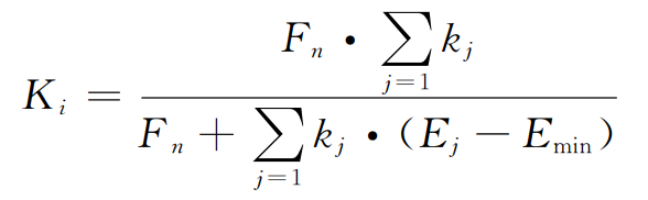
Where FN represents the normal force on the helical gear pair, n represents that at this rotation position, n pairs of thin plate helical gears participate in meshing, EJ represents the total meshing error of the jth pair of thin plate helical gears, which is equal to the sum of the tooth errors of the two meshing thin plate helical gears, I represents the rotation position serial number, and kJ represents the meshing stiffness of the jth pair of thin plate helical gears.
According to the formula, when FN = 0, the helical gear has no load transfer error Nlte:
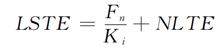
When FN ≠ 0, the load transfer error Lste of helical gear at any time:
Since EJ follows the gear angle ω J is related, so EJ changes from time to time. According to the formula, the helical gear comprehensive meshing stiffness Ki and gear tooth deviation have obvious nonlinear characteristics. Therefore, the gear tooth deviation and gear comprehensive meshing stiffness are coupled and affected by the gear tooth error.

The schematic diagram of comprehensive modification of tooth profile and tooth direction is shown in Figure 3. When only tooth profile modification is considered, the schematic diagram of the end face after helical gear modification is shown in Figure 3 (a). The dotted line represents the theoretical tooth profile of helical gear, the solid line represents the actual tooth profile of helical gear, and the tooth profile modification curve is a straight line. The modification amount of any point on the tooth profile curve after modification is:
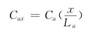
Where CA represents the maximum tooth profile modification amount, La represents the tooth profile modification length, and X is the distance from this point to the starting point of tooth profile modification.
When only tooth profile modification is considered, the schematic diagram of helical gear modification is shown in Figure 3 (b). The tooth profile modification curve is circular arc. The tooth profile modification amount CCX and circular arc radius r at any point of the modified tooth profile are respectively:
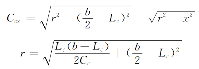
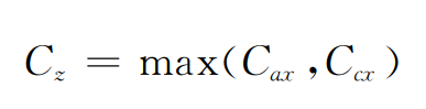
Where B is the tooth width, CC is the maximum tooth profile modification amount, LC is the tooth profile modification length, and X is the distance from this point to the center of tooth width. The comprehensive profile modification amount is: