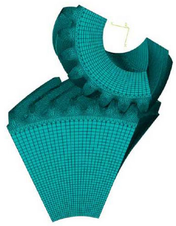
With the development of computer technology, the application of finite element method is more and more widely. Abaqus is used as the finite element simulation tool to calculate the time-varying meshing stiffness of gears. The finite element model of helical gear meshing at the input end of electric vehicle reducer is established as shown in the figure.

Since the contact line of the tooth surface will expand to a small area after the gear is deformed under load, it is difficult to accurately find the meshing position and extract the deformation of the point, so the quasi-static method is used for simulation in this section. That is to say, in the simulation, a small speed is given to the small gear, and a torque equal to the load torque is applied to the big gear. After the finite element simulation, the rotation angle data of the driving wheel and the driven wheel are extracted. At this time, the transmission error of the tooth pair under the load can be obtained, and it can be converted into the normal deformation of the gear according to formula (2-13). Since the real tooth surface data of the gear cannot be obtained, the finite element model in Fig. 2-4 is obtained from the standard gear model, that is, the influence of machining and installation errors is not considered in the finite element simulation in this section, only the bearing deformation of the gear is considered.

The normal load FN of tooth surface can be expressed by formula

According to the normal deformation and normal load obtained above, the meshing stiffness can be calculated

Where tout is the load torque, α, t is the pressure angle of the gear face, Z2 is the number of driven teeth, and Mn is the normal modulus.
