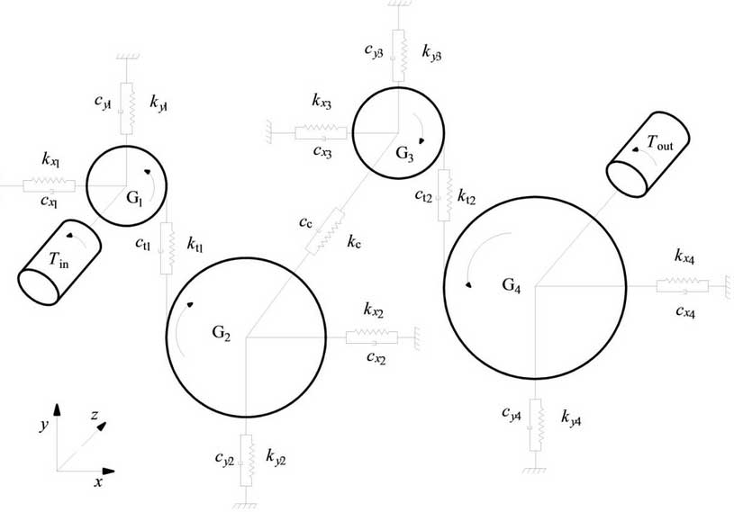
The centralized parameter method is used to establish the dynamic model of gear transmission system.This method has a small amount of calculation and is easy to iterate with the pre-and post-processing process. It is suitable for studying the time-varying characteristics of dynamic response and meets the research objectives of this paper.The centralized parameter method simplifies the system to a centralized parameter and considers the drive system as a series of springs, dampers and mass blocks connected together.Time-varying meshing stiffness due to crack growth is converted into an excitation applied to the system.

The gear drive system model is shown in Figure 1.The gears are arranged vertically along the engagement line. Gi (i=1, 2, 3, 4) is the theoretical rotation center of the gears respectively. The x-axis is perpendicular to the engagement line of the gears, the y-axis is parallel to the engagement line of the gears, and the z-axis is parallel to the direction of the drive shaft.Gear numbers 1, 2, 3 and 4 represent first-stage master and driven gears, second-stage master and driven gears respectively.
The differential equation of gear system dynamics can be expressed by equation (1):
{S {{{S *x+CxS\929;x+CxS929;x+KxSx=0MS y+CyS_x+KySy=0MS *y+CyS_y+KySy=Ctzezezezezezezezezezezezezezezezezein +KTheta TA Theta ++KTheTheTheta Theta Theta=RiCtzezezezezezezezezezezein 729;Theta+RiKtzezezezezezezezein Thein +RiKtThein Thein+IinThein+cin [in+cin (Theta929cout(theta_out_theta_4)+kout(theta out_theta 4)=Tout(1)
其中:M=diag(m1, m2, m3, m4);Cx=diag(cx1, cx2, cx3, cx4);Kx=diag(kx1, kx2, kx3, kx4);Sx=[sx1sx2sx3sx4];Cy=diag(cy1, cy2, cy3, cy4);Ky=diag(ky1, ky2, ky3, ky4);Sy=[sy1sy2sy3sy4];CtT=[ct1ct1 ct2 ct2];KtT=[kt1kt1 kt2 kt2];ξ=[ξy1 ξy2 ξy3 ξy4];I=diag(I1, I2, I3, I4);Cθ=diag(cin, cc, cc, cout);Kθ=diag(kin, kc, kc, Kout); theta=[theta 1the2theta 3the4]; zeta theta=[theta 1theta 2theta theta 3Zeta TA 4]; zeta i=Rethee-Ritheta i+y I-Y e; SXi and SYI are the degree of freedom of translation of the gear along the X and Y directions respectively; theta I is the degree of freedom of torsion of the gear; zeta y I and zeta I are the linear displacement and the angular displacement of the gear meshing line respectively; Ri is the radius of the gear base circle; KTI and CTI are the time-varying meshing stiffness and damping of the gear; the variables marked e below represent the gears with which they engage.
