Introduction
The thermal deformation and contact load of gears during transmission can cause meshing dislocation, which is an important factor affecting the contact stress, meshing stiffness, transmission efficiency, and failure damage of gears. Ideally, the contact stress of gears is evenly distributed along the tooth width direction, but due to the influence of deformation of various components in the transmission system, bearing clearance, and manufacturing and installation errors, the gears on the shaft can dislocate, resulting in changes in the contact area of the tooth surface and damage to the uniform distribution of load along the tooth width direction. The large and concentrated edge stress on the loaded tooth surface is generated. Most of the research on meshing dislocation in gear systems conducted by scholars at home and abroad is focused on analyzing the load-bearing contact aspects of gears. A detailed analysis and calculation of the system sources and influencing factors of meshing dislocation in electric vehicle reducer gears have been conducted, and it has been concluded that microscopic modification design of gears can reduce meshing dislocation deviation and compensate for its impact on gear eccentricity. A relevant model has been established to calculate and verify the effectiveness of tooth profile modification, tooth longitudinal modification, and diagonal modification in reducing fluctuations in gear pair STE under the influence of less than a certain amount of dislocation. Most of the current research is focused on the problem of tooth surface modification under ideal meshing conditions, but in reality, gear transmission is affected by many factors. This article considers the impact of random errors and systematic errors on meshing dislocation in the system, and conducts microscopic modification of gears. Through contact analysis and root stress analysis of different example models, the compensation effect of modification on meshing dislocation is compared and verified, providing a reference for further optimization of gear transmission design.
Analysis model and calculation example
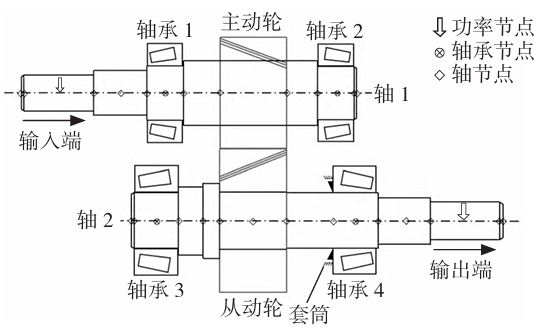
The schematic diagram of the gear transmission system analyzed and studied consists of a set of gear pairs, two pairs of bearings (both conical roller bearings), and two parallel rotating shafts. The power is transmitted from the left end of shaft 1 to the driving wheel, and then output from the right end of shaft 2 through the driven wheel. The maximum input torque is 450 N·m and the maximum speed is 7,500 r/min.
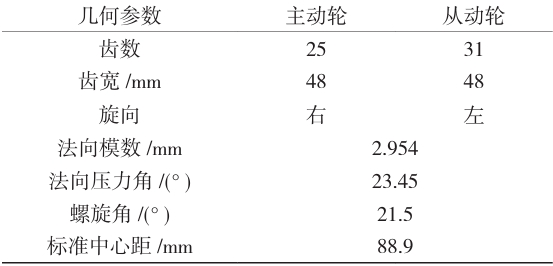
The gear pair is misaligned due to systematic errors but not modified; Example 2 modifies the gears in the case of systematic meshing misalignment; Example 3 introduces misalignment due to random errors but does not modify the gear pair (at this time, systematic meshing misalignment still exists); Example 4 modifies the gear pair in Example 3.
Misalignment of gear meshing
The misalignment of gear engagement is defined as the maximum separation between corresponding points of two gears along the direction of the gear width. The factors that cause gear misalignment are listed in detail using the symbol Fβx, and gear misalignment is divided into three types: parallel misalignment (center distance error), parallel misalignment MLOA along the meshing surface, and perpendicular misalignment MOLOA perpendicular to the meshing surface. The study analysis indicates that center distance errors will reduce the overlap of gear engagement and have a small impact on tooth-directional misalignment, which can be ignored; MOLOA will cause the actual contact surface to tilt, resulting in a smaller actual contact line length, but the reduction has little impact on tooth-directional misalignment, which is ignored here; here, MLOA is mainly considered, as this misalignment effect is equivalent to a spiral deviation. The situation where one end of the gear is far away from the meshing surface and the other end is deeply engaged will cause stress to concentrate towards the deeply engaged end, worsening the situation of tooth-directional misalignment.
Source of meshing dislocation
There are many factors that cause tooth misalignment and meshing dislocation, which can be roughly divided into two parts: manufacturing and installation errors of gears, and deformation and clearance of various components in the transmission system. In ISO, the misalignment caused by manufacturing and installation errors is recorded as fma, the misalignment caused by deformation and clearance of gears and supporting shafts is recorded as fsh, the misalignment caused by deformation of the box is recorded as fca, and the misalignment caused by bearing clearance and deformation is recorded as fbe. These errors can have a cumulative effect on the amount of misalignment and can compensate for each other. Deformation and clearance errors caused by factors such as load or temperature are systematic errors, among which factors that directly cause misalignment in the meshing surface include shaft bending, torsional deformation, gear deformation, bearing deformation, gear deformation caused by centrifugal force, and bearing clearance. Due to the low speed of this gear pair, the influence of gear deformation caused by centrifugal force is neglected, and the deformation of various components and bearing clearance can be obtained using computer simulation. Manufacturing and installation errors related to tolerances and accuracy are random errors, and installation errors are not considered here. Among the manufacturing errors, the helical slope deviation ∆fHβ and helical waviness deviation ∆ffβ have a significant impact on misalignment parallel to the meshing surface.
Misalignment of meshing
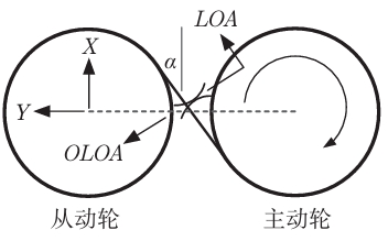
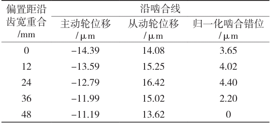
The calculation methods include calculation based on experimental measurement results (method A), calculation based on computer simulation (method B), and calculation based on influencing factor coefficients. Although different methods have an impact on the numerical results obtained, as long as the final misalignment morphology and the main factors affecting the misalignment are analyzed, the slight differences in numerical values have little impact on the analysis. Here, method B is used to simulate the meshing misalignment caused by systematic errors. Taking the origin of the gearbox as the coordinate origin O, the axis length direction is the Z axis (positive at the right end), the center distance direction of the gear pair is the Y axis (positive from the driving gear to the driven gear), and the normal direction of the YOZ plane is the X axis (right-hand rule). The continuous meshing surface of the gear is discretized into meshing points, and the tooth width is decomposed into n equally spaced measuring points along the axis of the gear shaft (n=5 is taken here). The linear displacements of the discrete points of the gear support shaft in the X and Y axes are calculated and denoted as MinX and MinY. The linear displacements of the measuring points of the gear pair are projected onto the direction of the meshing line of the gear pair (as shown in Figure 2, in the direction of LOA) to obtain the equivalent displacements of the two gears along the meshing line at that measuring point.
Gear shaping
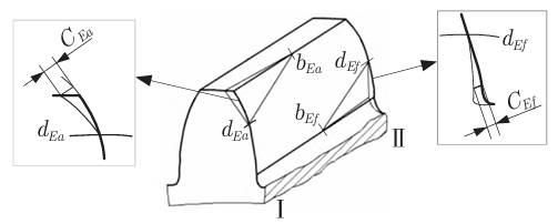
In order to improve the tooth surface contact performance of gear transmission under the influence of meshing misalignment and promote the reasonable distribution of tooth surface load, it is necessary to conduct micro-adjustment on the gear Observe the shape. The conventional methods of shape modification include tooth direction modification and tooth profile modification (two-dimensional modification). For helical gears, diagonal modification (three-dimensional modification) can also be performed The tooth profile modification is a modification along the tooth width direction, which can effectively avoid the problem of edge contact; the tooth profile modification is a modification along the involute The upward trimming is to avoid sudden changes in the load of the gear; the diagonal trimming is for the modification of the meshing angle of the helical gear, It can reduce the contact stress and load transmission error of the tooth surface, and reduce the impact of meshing and disengaging. The modification process mainly determines the following factors: the starting point of modification Position, direction of modification, length of modification, and maximum amount of modification.
Tooth alignment correction


Comparison of gear contact analysis
To verify the effectiveness of gear micro-modification in compensating for meshing misalignment, it is necessary to conduct tooth surface contact analysis and root stress analysis on the driving wheel in all cases as a basis for evaluation. The evaluation indicators involved are transmission error, contact spots on the working tooth surface of the driving wheel, and root stress of the driving wheel. The transmission error of the gear pair varies with the rotation angle of the driving wheel, and the transmission error here is represented by a linear displacement parallel to the direction of the meshing line. The results include transmission error values for five pairs of teeth. In case 1, the maximum transmission error value is TE=10.66 μm, the mean value is TE=9.71μm, and the fluctuation amount is ∆TE=1.71 μm. There is a significant peak in the transmission error, indicating that the tooth pair transition during meshing is not smooth enough. Compared to case 1, the transmission error in case 2 is generally higher due to the removal of material after gear modification. However, although the tooth surface contact spots and root stress are both stress analysis problems, the methods used in simulation calculations are different. The contact spots are analyzed using a tooth surface load-bearing contact analysis technique, which treats the root arc segment as an involute extension line from the base circle to the root circle. In order to more accurately analyze the bending stress of the root, a finite element method is used. The maximum load on the tooth surface occurs at the right end, with a contact spot length of approximately 23.8% of the full tooth width and a height of approximately 47.8% of the full tooth height. The root stress is distributed along the contact line and concentrated at the meshing end of the gear, indicating that the gear has a large meshing stiffness during meshing. There is no significant difference between the tooth surface and root, except for a slight increase in numerical values. Similarly, after modification in case 4, the stress amplitude decreases while the stress on the tooth surface and root is more evenly distributed.
conclusion
The main purpose of this study is to make targeted calculations and modifications to compensate for the effects of misalignment in gear pairs with different amounts of misalignment. The above results The results indicate that:
(1) Among the system factors, bearing deformation has the greatest impact on the amount of misalignment, and the effects of various factors sometimes overlap and sometimes cancel each other out;The spiral deviation has the greatest impact on the meshing misalignment among the random factors, and the effects of each factor are superimposed;
(2) The meshing misalignment caused by system factors is the dominant factor affecting the stability and load-bearing capacity of gear transmission;
(3) The combined modification method of tooth profile modification and diagonal modification has a good compensation effect on the influence of system factors on meshing misalignment,However, it has almost no compensation effect on the partial load caused by random meshing dislocation.
