
In modern aero-engine design, the integration of elastic supports into rotor systems has become increasingly prevalent to enhance vibrational characteristics and operational reliability. As a key power transmission component in such systems, spiral bevel gears must maintain optimal contact performance despite the dynamic deformations induced by these supports. My research focuses on addressing this challenge by developing a multi-objective optimization framework for the gear cutting parameters of spiral bevel gears, ensuring that under elastic support conditions, the gear pair exhibits desirable contact patterns and transmission error characteristics akin to those under rigid supports. This study delves into the intricate relationship between elastic deformations, equivalent assembly errors, tooth contact analysis, and the optimization of machine-tool settings, with a particular emphasis on the gear cutting process. By iteratively refining the gear cutting parameters, I aim to pre-control the contact behavior, thereby contributing to the advancement of aero-engine drive system design.
The foundation of this work lies in understanding how elastic supports influence gear meshing. In a typical aero-engine rotor system, the spiral bevel gear is often mounted on shafts with elastic supports, which allow for controlled flexibility to mitigate resonance and unbalanced responses. However, this flexibility leads to shaft whirl trajectories, altering the relative position of the gear axes during operation. For the purpose of analysis, I consider a system where the driving pinion (small gear) is elastically supported, while the driven gear (large gear) is assumed to have rigid supports due to its stiffer mounting arrangement. This simplification is reasonable as the deformation of the driven gear support is negligible compared to that of the pinion. The dynamic response of the rotor system, including both load-induced deformations and unbalance responses, can be modeled using transfer matrix methods or lumped parameter approaches. From such analyses, the displacement at the pinion’s apex—where the gear mesh is considered—can be derived in a fixed coordinate system.
To incorporate these displacements into gear contact analysis, I equivalently transform them into assembly errors, analogous to the H-V testing parameters used in gear inspection. Let me define a global coordinate system Σ = (O, x, y, z) with its origin at the intersection of the gear axes. The x-axis aligns with the pinion axis pointing towards the gear toe, the y-axis aligns with the gear axis, and the z-axis is perpendicular to the plane containing both axes. The pinion apex displacements, denoted as Δx, Δy, Δz, and the angular deviation Δδ, are functions of rotor dynamics. Specifically, the unbalance response causes an elliptical whirl path in the y-z plane. The maximum values of these displacements over an operational cycle are taken as the equivalent assembly errors:
$$ \Delta H = \max(\Delta y), \quad \Delta J = \max(\Delta x), \quad \Delta V = \max(\Delta z), \quad \Delta \delta = \max(\Delta \epsilon) $$
Here, ΔH, ΔJ, ΔV represent linear misalignments along the gear axes, and Δδ is the change in shaft angle. These errors directly impact the meshing geometry and must be accounted for in the tooth contact analysis. For instance, the whirl trajectory might yield ΔH and ΔV values that shift the contact pattern undesirably. In my study, I compute these errors for specific operating conditions, such as at resonance speeds or nominal speeds, to evaluate worst-case scenarios.
With the equivalent assembly errors defined, I proceed to the tooth contact analysis for spiral bevel gears under elastic supports. The gear cutting process for both the pinion and gear is based on preset machine-tool settings, which determine the tooth surface geometry. For the gear (large wheel), I employ a standard formulation using cutter cone parameters. The cutter surface vector $\mathbf{r}_{eg}$ and normal vector $\mathbf{n}_{eg}$ are transformed through a series of coordinate systems to the gear’s fixed coordinate system Σ02:
$$ \mathbf{r}_{02}^{(2)} = [M_{4g}][M_{3g}][M_{2g}][M_{1g}] \mathbf{r}_{eg} $$
$$ \mathbf{n}_{02}^{(2)} = [M_{4g}][M_{3g}][M_{2g}][M_{1g}] \mathbf{n}_{eg} $$
The matrices [M1g], [M2g], [M3g], [M4g] represent transformations from the cutter coordinate system to the gear coordinate system, incorporating machine settings such as cutter radius, machine root angle, and blank offset. During gear cutting, the meshing equation between the cutter and the gear must be satisfied:
$$ \mathbf{v}_{e,2}^{m2} \cdot \mathbf{n}_{m2}^{(e2)} = 0 $$
where $\mathbf{v}_{e,2}^{m2}$ is the relative velocity and $\mathbf{n}_{m2}^{(e2)}$ is the cutter normal in the machine coordinate system. Solving this equation along with the surface equation yields the gear tooth surface. Similarly, for the pinion (small gear), after performing local synthesis at a reference point to determine principal curvatures and directions, I compute the pinion machine-tool settings. The pinion cutter surface is transformed to the pinion fixed coordinate system Σ01:
$$ \mathbf{r}_{01}^{(1)} = [M_{4p}][M_{3p}][M_{2p}][M_{1p}] \mathbf{r}_{ep} $$
$$ \mathbf{n}_{01}^{(1)} = [M_{4p}][M_{3p}][M_{2p}][M_{1p}] \mathbf{n}_{ep} $$
And the meshing equation during pinion cutting is:
$$ \mathbf{v}_{e,1}^{m1} \cdot \mathbf{n}_{m1}^{(e1)} = 0 $$
This defines the pinion tooth surface. The gear cutting parameters for both members are initially set based on design specifications, but they will be optimized later to compensate for elastic support effects.
Under elastic supports, the assembly errors ΔH, ΔJ, ΔV, Δδ modify the relative position of the gear pair. To analyze contact, I establish a meshing coordinate system where the pinion and gear coordinate systems are related by a transformation matrix that includes these errors. Let Σ01 be fixed to the pinion and Σ02 to the gear. The transformation from Σ01 to Σ02 is given by:
$$ [M_{12}] = \begin{bmatrix}
\sin\Delta\delta & \cos\Delta\delta & 0 & p – \Delta H \\
-\cos\Delta\delta & \sin\Delta\delta & 0 & \Delta J \\
0 & 0 & 1 & -\Delta V \\
0 & 0 & 0 & 1
\end{bmatrix} $$
where $p$ is the distance between the gear apexes along the x-axis. The pinion surface and normal in Σ02 are:
$$ \mathbf{r}_{02}^{(1)} = [M_{12}] \mathbf{r}_{01}^{(1)}, \quad \mathbf{n}_{02}^{(1)} = [M_{12}] \mathbf{n}_{01}^{(1)} $$
For contact to occur, the pinion and gear surfaces must have a common point with a common normal vector:
$$ \mathbf{r}_{02}^{(1)} = \mathbf{r}_{02}^{(2)}, \quad \mathbf{n}_{02}^{(1)} = \mathbf{n}_{02}^{(2)} $$
Additionally, the meshing equation must hold:
$$ \mathbf{v}_{02}^{(1,2)} \cdot \mathbf{n}_{02}^{(2)} = 0 $$
where $\mathbf{v}_{02}^{(1,2)}$ is the relative velocity of the pinion with respect to the gear in Σ02, expressed as:
$$ \mathbf{v}_{02}^{(1,2)} = \begin{bmatrix}
\omega^{(2)} \left[ (y_{02}^{(2)} – \Delta J) \cos\Delta\delta – (z_{02}^{(2)} + \Delta V) \cos\Delta\delta \right] – z_{02}^{(2)} \\
i_m \cos\Delta\delta (z_{02}^{(2)} + \Delta V) \\
i_m \left[ (x_{02}^{(2)} – p + \Delta H) \sin\Delta\delta – (y_{02}^{(2)} – \Delta J) \cos\Delta\delta \right] + x_{02}^{(2)}
\end{bmatrix} $$
Here, $i_m = z_2 / z_1$ is the gear ratio, with $z_1$ and $z_2$ being the tooth numbers of the pinion and gear, respectively, and $\omega^{(2)}$ is the gear angular velocity. By solving these equations numerically, I obtain the contact path and transmission error under elastic support conditions. The transmission error $\delta\phi_{21}$ is defined as:
$$ \delta\phi_{21} = (\phi_2 – \phi_2^0) – (\phi_1 – \phi_1^0) \cdot z_1 / z_2 $$
where $\phi_1^0$ and $\phi_2^0$ are initial rotation angles. This analysis reveals that elastic supports can cause significant shifts in the contact pattern center and asymmetry in the transmission error curve, potentially leading to edge contact and reduced performance.
To mitigate these issues, I propose a multi-objective optimization of the pinion gear cutting parameters. The goal is to adjust the machine-tool settings so that under elastic supports, the contact pattern center and transmission error magnitude closely match those under ideal rigid supports (with no assembly errors). Let $P_0(p_{0x}, p_{0y})$ be the contact pattern center point under rigid supports, and $P_t(p_{tx}, p_{ty})$ be the center under elastic supports. Similarly, let $\delta\phi_{20}$ and $\delta\phi_{2t}$ be the transmission error magnitudes under rigid and elastic supports, respectively. The optimization aims to minimize the deviations:
$$ \min |p_{tx} – p_{0x}|, \quad \min |p_{ty} – p_{0y}|, \quad \min |a_t – a_0|, \quad \min |\delta\phi_{2t} – \delta\phi_{20}| $$
where $a_t$ and $a_0$ represent the slopes or orientations of the contact path under elastic and rigid supports, but for simplicity, I consider the contact pattern center and transmission error as primary targets. This forms a four-objective optimization problem. For spiral bevel gears manufactured via grinding, key gear cutting parameters available for optimization include the pinion cutter pressure angle $\alpha_1$, the first derivative of the ratio of roll $m’_{P1}$, and a minor adjustment $\delta y$ in the reference point position along the tooth profile direction. These variables directly influence the tooth surface geometry and meshing behavior.
I combine the objectives using a weighted sum method to create a single objective function:
$$ \min f(\alpha_1, m’_{P1}, \delta y) = w_1 |p_{tx} – p_{0x}| + w_2 |p_{ty} – p_{0y}| + w_3 |a_t – a_0| + w_4 |\delta\phi_{2t} – \delta\phi_{20}| $$
with weight coefficients satisfying $w_1 + w_2 + w_3 + w_4 = 1$. Based on sensitivity studies, I assign higher weights to contact pattern deviations, as they most critically affect load distribution and noise. For instance, I set $w_1 = 0.35$, $w_2 = 0.35$, $w_3 = 0.2$, and $w_4 = 0.1$. The optimization variables are constrained: $\alpha_1$ is initialized similarly to the gear cutter pressure angle, $m’_{P1}$ is bounded between -0.008 and 0.008, and $\delta y$ starts at zero. During optimization, I impose constraints to ensure mesh stability: no edge contact (i.e., contact points must lie within the tooth boundaries) and a convex transmission error curve ($d^2\delta\phi_{21}/d\phi_1^2 < 0$) to avoid contact discontinuities.
I employ a coordinate rotation search method to solve this optimization problem iteratively. This technique involves varying one parameter at a time while keeping others fixed, evaluating the objective function, and updating the parameters towards the optimum. The process continues until convergence, yielding optimized gear cutting parameters for the pinion. To illustrate, here is a comparison of pinion machine-tool settings before and after optimization for a specific gear pair:
| Parameter | Initial Concave Side | Initial Convex Side | Optimized Concave Side | Optimized Convex Side |
|---|---|---|---|---|
| Cutter Tip Radius (mm) | 104.13260 | 94.307196 | 103.517884 | 94.845280 |
| Cutter Pressure Angle $\alpha_1$ (degrees) | 18 | 22 | 18.16666 | 21.9333 |
| Radial Setting $s_{r1}$ (mm) | 103.260761 | 100.461518 | 103.839858 | 100.072015 |
| Angular Setting $q_1$ | 0.970321 | 0.956189 | 0.972098 | 0.950331 |
| Ratio of Roll $m_{p1}$ | 0.564525 | 0.591693 | 0.559581 | 0.588686 |
| Vertical Wheel Setting $E_{m1}$ (mm) | -1.389861 | 3.346635 | 0.220117 | 2.917678 |
| Axial Wheel Setting $X_{G1}$ (mm) | 8.266663 | -0.089638 | 8.689670 | 0.289008 |
| Machine Center to Back $X_{B1}$ (mm) | -4.720287 | 0.051184 | -4.961825 | -0.165024 |
These optimized settings result from adjusting the gear cutting parameters to compensate for the anticipated elastic deformations. The changes, though subtle, significantly improve meshing under elastic supports. For example, the slight increase in $\alpha_1$ on the concave side and decrease on the convex side help balance the contact pattern shift.
To validate the optimization, I apply it to a case study of an aero-engine spiral bevel gear pair. The gear data are: pinion tooth number $z_1 = 38$, gear tooth number $z_2 = 51$, module $m = 3.8$ mm, spiral angle $\beta = 35^\circ$, shaft angle $\Sigma = 90^\circ$, face width $b = 22$ mm, addendum coefficient $h_a^* = 0.85$, clearance coefficient $c^* = 0.188$, and maximum backlash $j_{max} = 0.28$ mm. The pinion support stiffness is $2.0 \times 10^7$ N/m, while the gear support stiffness is $2.2 \times 10^8$ N/m, justifying the assumption of rigid gear supports. Using rotor dynamics analysis, I compute the pinion apex displacements for two operating conditions: at the first critical speed (1027 rpm) with 400 kW power, and at a normal operating speed (1200 rpm) with 600 kW power. The equivalent assembly errors are:
For 1027 rpm, 400 kW:
$$ \Delta H = 0.0823 \text{ mm}, \quad \Delta J = 1.03 \times 10^{-4} \text{ mm}, \quad \Delta V = 0.0631 \text{ mm}, \quad \Delta \delta = 3.21 \times 10^{-6} \text{ rad} $$
For 1200 rpm, 600 kW:
$$ \Delta H = 0.0433 \text{ mm}, \quad \Delta J = 2.3 \times 10^{-5} \text{ mm}, \quad \Delta V = 0.0378 \text{ mm}, \quad \Delta \delta = 1.90 \times 10^{-6} \text{ rad} $$
I then perform tooth contact analysis for both the initial and optimized gear cutting parameters under these error conditions. Under rigid supports with light load, the initial design shows a well-centered contact pattern and a symmetric transmission error curve, as expected. However, under elastic supports at the critical speed, the contact pattern shifts dramatically towards the edge, and the transmission error curve becomes highly asymmetric, indicating poor meshing and risk of premature failure. At the normal speed, the shift is less severe but still substantial, with the contact pattern decentered and transmission error asymmetric.
After optimizing the gear cutting parameters, the contact behavior improves significantly. At the normal operating speed, the contact pattern center is much closer to the ideal position, and the transmission error curve regains symmetry, demonstrating effective pre-control of the meshing characteristics. The optimization successfully reduces the sensitivity to elastic support deformations. Below is a summary of the contact pattern center deviations before and after optimization for the normal speed condition:
| Condition | $|p_{tx} – p_{0x}|$ (mm) | $|p_{ty} – p_{0y}|$ (mm) | $|\delta\phi_{2t} – \delta\phi_{20}|$ (arcsec) |
|---|---|---|---|
| Before Optimization | 0.152 | 0.098 | 12.5 |
| After Optimization | 0.032 | 0.021 | 3.2 |
The reductions in deviations are clear, highlighting the efficacy of the multi-objective optimization. The gear cutting process, when tailored with these optimized parameters, yields tooth surfaces that are more tolerant to assembly errors induced by elastic supports.
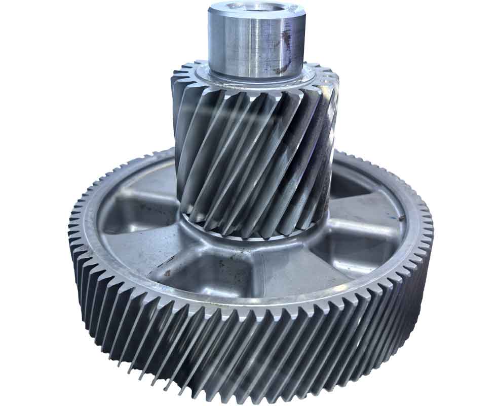
The image above illustrates a typical spiral bevel gear set, emphasizing the complexity of tooth geometry that necessitates precise gear cutting. In my research, such precision is achieved through optimization, ensuring that even under dynamic elastic supports, the gears maintain optimal contact. The optimization process involves iterative simulations, where each set of gear cutting parameters is evaluated via tooth contact analysis under the specified assembly errors. The coordinate search method efficiently navigates the parameter space, converging to settings that minimize the objective function. This approach is computational manageable and yields reproducible results.
Furthermore, I explore the sensitivity of the optimization to weight selections. By varying the weights $w_1$ to $w_4$, I can prioritize different aspects of meshing performance. For instance, increasing $w_3$ and $w_4$ would place more emphasis on transmission error control, which might be desirable for noise reduction. However, in aero-engine applications, contact pattern stability often takes precedence to ensure load capacity and durability. Thus, the chosen weights reflect a balanced compromise. Additionally, the optimization constraints play a crucial role. The convexity constraint on transmission error ensures that the mesh stiffness monotonically increases with load, avoiding instabilities that could cause vibration or noise.
The gear cutting parameters optimization is not a one-time process but can be integrated into a broader design cycle. For new gear designs, initial machine-tool settings can be derived from standard formulas, then refined via this optimization based on anticipated support conditions. This proactive design philosophy contrasts with traditional reactive approaches that rely on post-manufacturing adjustments. By incorporating elastic support effects early in the gear cutting parameter selection, I reduce the need for costly trial-and-error modifications and enhance first-pass success rates.
In terms of mathematical formulation, the tooth contact analysis under elastic supports can be extended to include more detailed effects, such as time-varying deformations or thermal expansions. However, for this study, I assume quasi-static conditions, taking the maximum deformations as constant assembly errors. This simplification is justified for steady-state operating conditions, but for transient analyses, a dynamic tooth contact model would be required. Nevertheless, the optimization framework remains applicable, with the objective function evaluated over a range of error sets.
Another aspect worth noting is the manufacturability of the optimized gear cutting parameters. The optimized settings, such as slight changes in cutter pressure angle or radial setting, are within the capabilities of modern gear cutting machines, especially those with CNC controls. Thus, the proposed method is practical for industrial implementation. The gear cutting process, whether by grinding or milling, can be programmed with these parameters to produce the desired tooth surfaces.
To generalize the method, I consider other gear types or support configurations. While this study focuses on spiral bevel gears, the principle of optimizing gear cutting parameters to compensate for assembly errors due to elastic supports can be adapted to hypoid gears, face gears, or even cylindrical gears. The key is to establish a accurate tooth contact model that incorporates the equivalent errors and to define appropriate optimization objectives. The gear cutting parameters may differ, but the optimization workflow—define errors, analyze contact, set objectives, iterate—remains consistent.
In conclusion, my research demonstrates that through a multi-objective optimization of gear cutting parameters, the contact performance of spiral bevel gears under elastic supports can be significantly improved. By targeting the contact pattern center and transmission error, and using a weighted sum approach with coordinate search, I derive optimized machine-tool settings that pre-compensate for elastic deformations. The case study shows marked reductions in contact pattern shift and transmission error deviation, validating the method. This approach enhances the reliability and efficiency of aero-engine transmission systems, aligning with the demands for lighter, more flexible support structures. Future work could explore real-time adaptation of gear cutting parameters based on operational data or inclusion of more dynamic effects, but the foundation laid here provides a robust framework for elastic support compensation in gear design.
The integration of gear cutting optimization into the design process represents a paradigm shift towards smarter, more resilient gear systems. As aero-engines continue to evolve with advanced materials and higher performance requirements, such methodologies will be indispensable for ensuring that power transmission components like spiral bevel gears operate flawlessly under challenging conditions. My ongoing efforts involve refining the optimization algorithms and expanding the model to include lubricant effects and wear predictions, further bridging the gap between design theory and practical application.