The two-dimensional diagram of upper and lower dies of spiral bevel gear is shown in Figure 1.
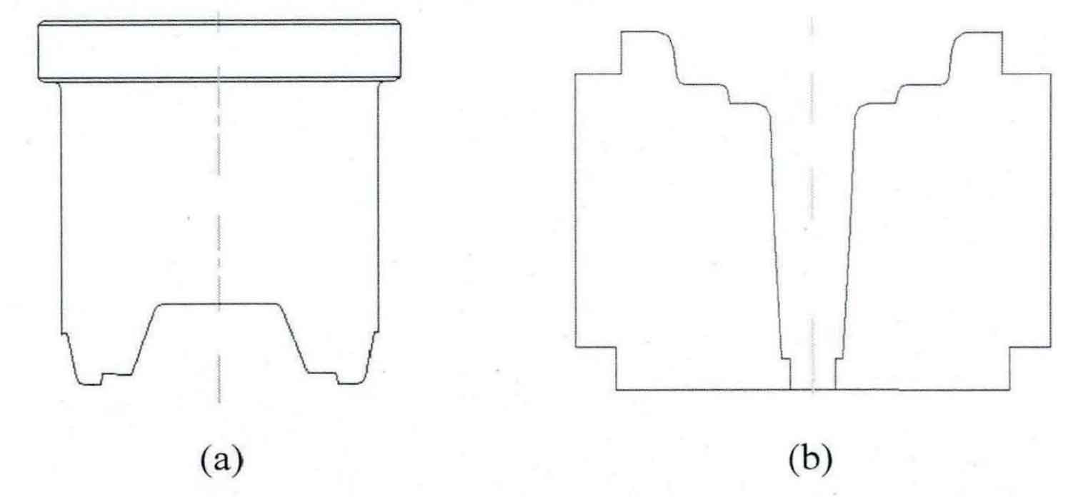
1.Establishment of mold geometric model
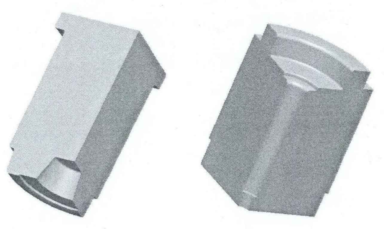
According to the two-dimensional diagram of the upper and lower dies of spiral bevel gear, the 1 / 4 geometric model of the upper and lower dies is established, as shown in Figure 2.
2.Establishment of finite element model of die forging process
After the extrusion process of spiral bevel gear blank is completed, enter the pre-processing module of Defrom-3D, delete the mesh and geometric model of upper and lower dies in the extrusion process, and import the geometric model of upper and lower dies in the die forging process, so as to establish the finite element model of die forging process. The establishment of finite element model of die forging process includes the following contents:
(1) Mesh the upper and lower dies of spiral bevel gear. After division, the number of upper mold grids is 60883 and the number of lower mold grids is 137789.
(2) The upper and lower dies of spiral bevel gear are set as rigid bodies, the initial temperature is 250 ° C, and the material is 4Cr5MoSiV1.
(3) The simulation step size is set to 0.15mm and the number of simulation steps is set to 500. The conjugate gradient method is used as the solution algorithm and the direct iterative method is used as the iterative method.
(4) The friction coefficient is 0.3, and the forging equipment adopts screw press.
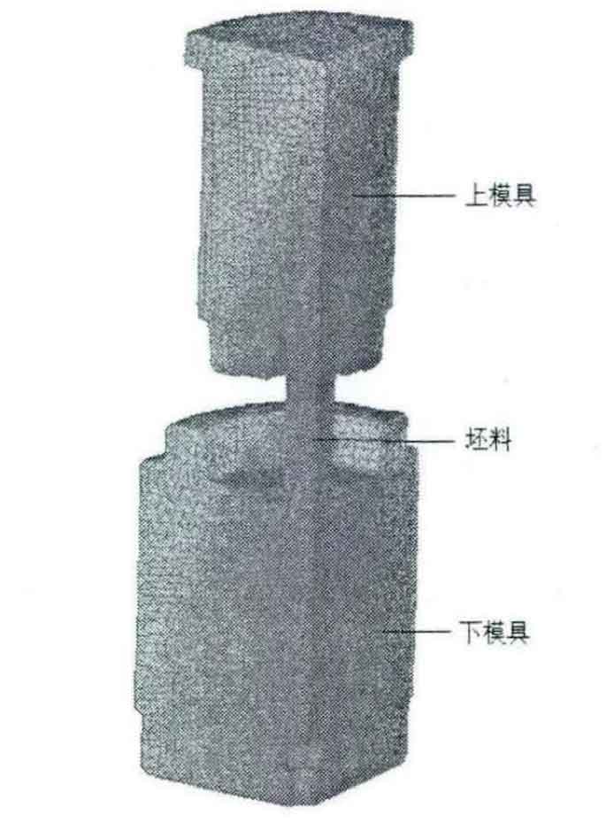
The final finite element model is shown in Figure 3.
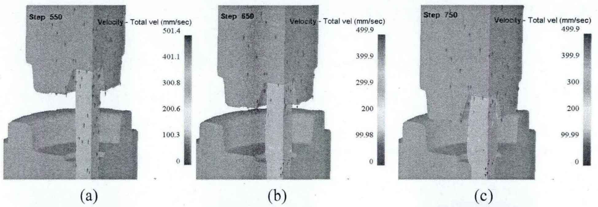
3.Metal flow law in die forging process
The metal velocity vector diagram of each stage in the die forging process of spiral bevel gear blank is shown in Figure 4. Because the numerical simulation of spiral bevel gear blank die forging process is based on the numerical simulation of extrusion process, the numerical simulation of spiral bevel gear blank die forging process starts from step 549. FIG. 4A is the metal flow velocity vector diagram of step, FIG. 4B to Fig. 4E are the metal flow velocity vector diagram of the intermediate process, and Fig. 4f is the metal flow velocity vector diagram at the completion of die forging.
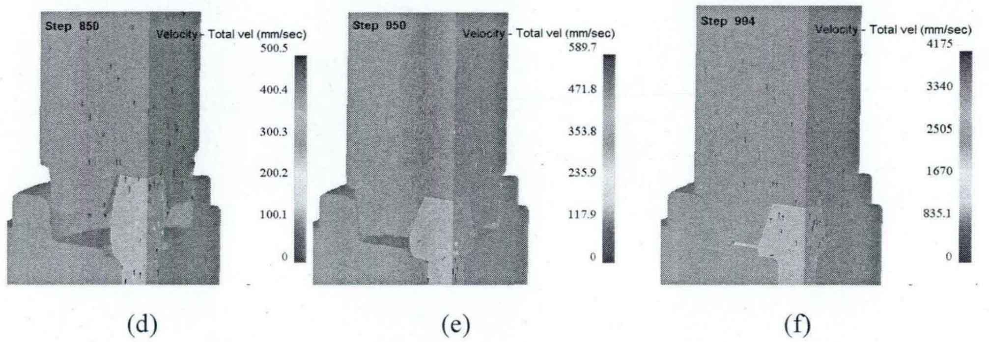
4.Equivalent stress analysis during final forging
The stress distribution of forgings during final forging of spiral bevel gear blank is shown in Figure 5. The overall stress of the forging is between 86-656mpa, and the large stress occurs at the bottom, outer edge and flash of the forging. There is a sudden increase in stress at the step as shown in Figure 6.
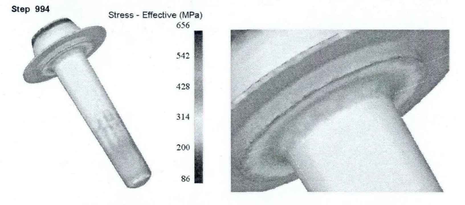
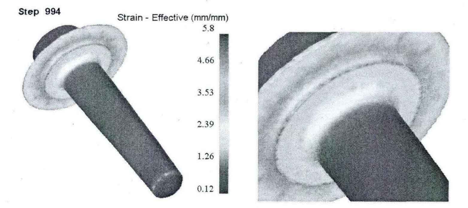
5.Analysis of equal effect variation during final forging
The distribution of equivalent strain of forgings during final forging of spiral bevel gear blank is shown in Figure 7. The overall strain of the forging is between 0.12-5.8, and the large strain occurs at the outer edge and flash. There is a sudden increase in strain at the step as shown in Figure 8.
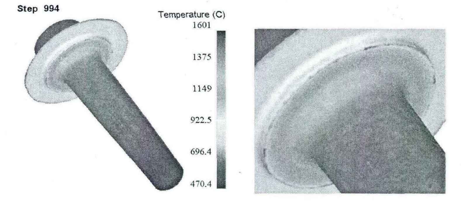
6.Temperature analysis during final forging
The temperature distribution of forgings during final forging of spiral bevel gear blank is shown in Figure 9. The overall temperature of the forging is 470-1601 ° C, and the high temperature occurs at the outer edge and flash. There is a sudden increase in temperature at the step as shown in Figure 10.