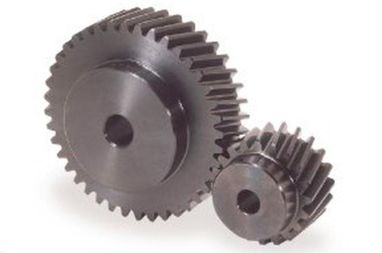
Helical gear is favored in many industrial applications due to their ability to transmit high loads smoothly and quietly. Optimizing the geometry of helical gear is crucial for enhancing their performance and durability, especially in high load applications. This article explores the key aspects of helical gear geometry optimization, the benefits of such optimizations, and practical guidelines for engineers.

Introduction
Helical gear is characterized by their angled teeth, which engage gradually, reducing noise and vibration while providing higher load-carrying capacity than spur gear. Optimizing the geometry of helical gear involves adjusting parameters such as helix angle, pressure angle, and tooth profile to achieve the best performance under high load conditions. This article provides an in-depth analysis of these parameters and their impact on helical gear performance.
Key Aspects of Helical Gear Geometry
Helix Angle
The helix angle is the angle between helical gear teeth and the gear axis. It plays a significant role in determining the load distribution and contact ratio.
| Helix Angle | Impact on Performance |
|---|---|
| 15° to 20° | Common range for general applications |
| 20° to 35° | Higher load capacity, smoother operation |
| Above 35° | Increased axial forces, requires robust bearings |
An optimal helix angle ensures better load distribution and higher efficiency.
Pressure Angle
The pressure angle is the angle between the line of action and the normal to helical gear teeth. It affects the strength and contact stress of the gear teeth.
| Pressure Angle | Impact on Performance |
|---|---|
| 14.5° | Lower contact stress, less load capacity |
| 20° | Balanced strength and stress distribution |
| 25° | Higher strength, increased contact stress |
Selecting an appropriate pressure angle balances helical gear strength and wear resistance.
Module and Tooth Profile
The module is a measure of the size of helical gear teeth. The tooth profile, often based on the involute curve, determines the gear’s contact characteristics.
| Parameter | Impact on Performance |
|---|---|
| Module | Larger modules for higher load capacity |
| Tooth Profile | Involute profiles for smooth engagement |
Optimizing these parameters ensures helical gear can handle high loads without excessive wear.
Benefits of Geometry Optimization
Improved Load Distribution
Optimized helical gear geometry ensures that the load is evenly distributed across helical gear teeth, reducing stress concentrations and wear.
| Benefit | Description |
|---|---|
| Even Load Distribution | Reduces stress on individual teeth, prolongs gear life |
| Lower Stress | Minimizes risk of gear failure under high loads |
Improved load distribution enhances the reliability and lifespan of helical gear.
Enhanced Efficiency
Reducing friction and optimizing contact patterns result in higher efficiency, which is crucial for high load applications.
| Benefit | Description |
|---|---|
| Reduced Friction | Less energy loss, higher operational efficiency |
| Smoother Operation | Lower noise and vibration levels |
Enhanced efficiency leads to better performance and lower energy consumption.
Increased Durability
Optimizing gear geometry increases the durability of helical gear by reducing wear and preventing premature failure.
| Benefit | Description |
|---|---|
| Wear Resistance | Prolongs the operational life of the gears |
| Strength | Higher load-carrying capacity without failure |
Increased durability ensures that helical gear can withstand harsh operating conditions.
Practical Guidelines for Geometry Optimization
Design Considerations
Engineers must consider various factors when optimizing helical gear geometry for high load applications.
| Consideration | Impact on Optimization |
|---|---|
| Operating Conditions | Temperature, load, speed |
| Material Properties | Strength, hardness, wear resistance |
| Manufacturing Constraints | Precision, cost, feasibility |
Taking these factors into account ensures a well-rounded optimization approach.
Simulation and Analysis
Using advanced simulation tools, such as Finite Element Analysis (FEA), helps in predicting gear performance under various load conditions.
| Tool | Benefits |
|---|---|
| FEA | Identifies stress concentrations, optimizes design |
| CFD | Analyzes lubrication flow, improves cooling |
Simulation and analysis provide valuable insights for optimizing helical gear geometry.
Testing and Validation
Prototyping and testing the optimized helical gear designs under real-world conditions validate the theoretical models and simulations.
| Method | Benefits |
|---|---|
| Prototyping | Real-world performance assessment |
| Load Testing | Verifies load-carrying capacity |
Testing ensures that the optimized design performs as expected in actual applications.
Case Studies
- Automotive Transmissions: An automotive manufacturer optimized the helix and pressure angles of helical gear in their transmission systems, resulting in improved load distribution and reduced noise. This led to enhanced performance and longer transmission life.
- Wind Turbine Gearboxes: A wind turbine manufacturer used FEA to optimize helical gear geometry, achieving better load handling and reduced maintenance costs due to increased gear durability.
- Industrial Machinery: An industrial machinery company implemented optimized helical gear profiles, resulting in higher efficiency and lower operational costs for heavy-duty applications.
Conclusion
Optimizing helical gear geometry is essential for enhancing performance and durability in high load applications. By carefully adjusting parameters such as helix angle, pressure angle, and tooth profile, and utilizing advanced simulation and testing techniques, engineers can develop gears that offer improved load distribution, higher efficiency, and increased durability. These optimizations ensure that helical gears meet the demands of modern high-performance applications, providing reliable and efficient power transmission.
