
I have developed a parametric computer-aided design system for screw gear drives because the design of a screw gear pair involves many coupled parameters, large data tables, and repeated geometric computations. A screw gear transmission, commonly realized as a cylindrical worm and a worm wheel, transfers motion and torque between two non-intersecting shafts. The design process for a screw gear requires the simultaneous selection of the module, pressure angle, diameter quotient, number of starts, number of worm wheel teeth, lead angle, and material combination. When I began this work, I found that manual calculation for a screw gear was slow, error-prone, and difficult to reuse. Therefore, I built a software module that integrates AutoLISP, AutoCAD, SQL Server, numerical interpolation, and parametric drawing so that a designer can enter a small set of sensitive parameters and obtain a complete screw gear design, a two-dimensional part drawing, and a three-dimensional model.
My central idea is that a screw gear drive should not be treated as a collection of isolated formulas. Instead, I treat the screw gear drive as an object with attributes, behaviors, and constraints. The attributes include geometric dimensions, material properties, and thermal limits. The behaviors include calculation of the lead angle, efficiency, sliding velocity, and heat balance. The constraints include standard module values, recommended diameter quotients, minimum tooth counts, and permissible oil temperature. By encapsulating these elements in an AutoLISP-based parametric environment, I can generate a screw gear design that is consistent, repeatable, and easy to modify.
Design Requirements and Software Architecture
I organized the screw gear design system into four major modules: table and chart processing, geometric parameter design, heat balance calculation, and automatic drawing. Each module communicates with the others through a shared database and a set of global AutoLISP variables. The architecture of my screw gear system follows an object-oriented development process. I first performed requirement analysis, then abstracted the screw gear model, then divided the system into modules, then programmed and tested each module, and finally implemented maintenance functions. This sequence helped me avoid the common problem of writing drawing code before the geometric relations of the screw gear were fully defined.
The screw gear transmission design algorithm receives known parameters such as input power, input speed, transmission ratio, duty cycle, and material selection. It then computes the geometric parameters, checks the contact and bending strength, performs the heat balance calculation, and writes the results to the database. The parametric drawing module reads the same results and generates the screw gear drawing. The following table summarizes the modules and their responsibilities in my screw gear system.
| Module | Primary Input | Primary Output | Dependencies |
|---|---|---|---|
| Table and chart processing | Standard tables, material data, interpolation nodes | Interpolated coefficients and correction factors | SQL Server, AutoLISP interpolation functions |
| Geometric parameter design | Power, speed, ratio, material, duty | Module, diameter quotient, lead angle, tooth counts, dimensions | Table module, strength equations |
| Heat balance calculation | Efficiency, power loss, housing area, ambient temperature | Oil temperature, required cooling area | Geometric module, material data |
| Automatic drawing | Computed dimensions, drawing template | Two-dimensional DWG, three-dimensional model | AutoCAD, AutoLISP, geometric module |
I use AutoCAD as the development platform because it is widely available and because its open architecture supports Visual LISP and ActiveX automation. I use SQL Server as the database because a screw gear design requires many standard tables, material property tables, and recommended parameter ranges. I use AutoLISP as the programming language because it can directly create and modify AutoCAD entities, and because it can implement dialog interfaces, file input and output, and mathematical computation. With this combination, my screw gear system can calculate all characteristic values and store them in the database, and then AutoLISP can retrieve the relevant geometric parameters to generate a part drawing or a three-dimensional model.
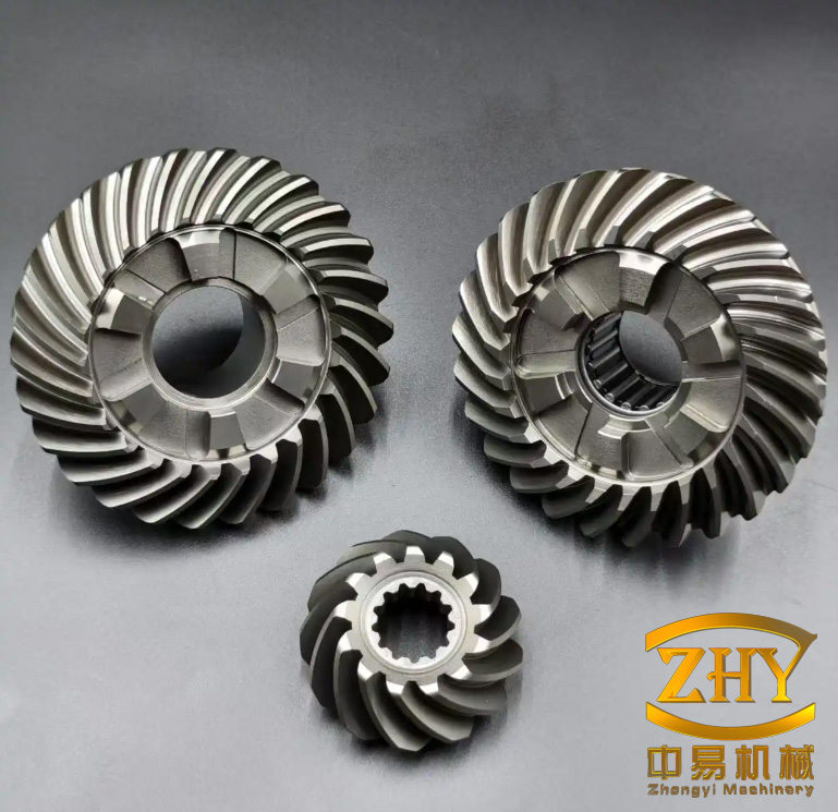
Mathematical Foundation of Screw Gear Geometry
I begin the mathematical modeling of a screw gear by defining the basic relationships among the screw gear parameters. For a cylindrical screw gear drive, the transmission ratio is determined by the ratio of the number of worm wheel teeth to the number of worm starts. I write this as
$$ i = \frac{n_1}{n_2} = \frac{z_2}{z_1} $$
where \(n_1\) is the rotational speed of the screw gear worm, \(n_2\) is the rotational speed of the screw gear wheel, \(z_1\) is the number of starts of the screw gear worm, and \(z_2\) is the number of teeth of the screw gear wheel. The module of the screw gear is defined from the circular pitch on the wheel as
$$ m = \frac{p_t}{\pi} $$
where \(p_t\) is the transverse pitch of the screw gear wheel. The diameter quotient \(q\) is one of the most important parameters for a screw gear because it controls the worm diameter for a given module. I define it as
$$ q = \frac{d_1}{m} $$
where \(d_1\) is the reference diameter of the screw gear worm. The lead angle \(\gamma\) of the screw gear is then obtained from
$$ \gamma = \arctan\left(\frac{z_1}{q}\right) = \arctan\left(\frac{m z_1}{d_1}\right) $$
The lead of the screw gear worm is
$$ p_z = \pi m z_1 $$
The reference diameter of the screw gear wheel is
$$ d_2 = m z_2 $$
The center distance of the screw gear pair is
$$ a = \frac{d_1 + d_2}{2} = \frac{m(q + z_2)}{2} $$
For a screw gear with a non-standard center distance, I must modify either the diameter quotient or the number of teeth. In my parametric system, I allow the user to enter the desired center distance, and I search the standard tables for the nearest valid combination of \(q\) and \(z_2\) that satisfies the strength and thermal constraints.
The helical line of the screw gear worm is also important for three-dimensional modeling. I represent a point \(M(x,y,z)\) on the screw gear helical line as
$$ x = \left(r_0 + \frac{h_g \alpha}{2\pi}\right)\cos\alpha $$
$$ y = \left(r_0 + \frac{h_g \alpha}{2\pi}\right)\sin\alpha $$
$$ z = \pm \frac{v_g \alpha}{2\pi} $$
where \(r_0\) is the base radius of the screw gear worm, \(\alpha\) is the helix angle parameter, \(v_g\) is the lead, and \(h_g\) is the radial increment. I define \(h_g\) as
$$ h_g = \left| (r_1 – r_0) n \right| $$
where \(r_1\) is the outer radius of the screw gear worm and \(n\) is the number of turns. The sign of \(z\) is positive for a right-hand screw gear and negative for a left-hand screw gear. These equations allow me to generate the screw gear helix directly in AutoLISP and to create a three-dimensional polyline or surface.
The following table lists the principal geometric symbols and their meanings in my screw gear design system.
| Symbol | Meaning | Unit | Typical Range |
|---|---|---|---|
| \(m\) | Axial module of the screw gear | mm | 1 to 20 |
| \(q\) | Diameter quotient of the screw gear worm | dimensionless | 6 to 18 |
| \(z_1\) | Number of starts of the screw gear worm | dimensionless | 1, 2, 4, 6 |
| \(z_2\) | Number of teeth of the screw gear wheel | dimensionless | 30 to 80 |
| \(\gamma\) | Lead angle of the screw gear | degree | 3 to 30 |
| \(d_1\) | Reference diameter of the screw gear worm | mm | \(mq\) |
| \(d_2\) | Reference diameter of the screw gear wheel | mm | \(m z_2\) |
| \(a\) | Center distance of the screw gear pair | mm | \(m(q+z_2)/2\) |
Parameter Selection and Database Structure
I store the standard data for screw gear design in SQL Server. The database includes tables for modules, diameter quotients, material properties, allowable stresses, efficiency coefficients, heat transfer coefficients, and interpolation nodes. When I design a screw gear, I do not hard-code the standard values into the AutoLISP program. Instead, I query the database and use the retrieved values. This makes the screw gear system easier to maintain and extend.
The main database tables in my screw gear system are shown below.
| Table Name | Key Fields | Purpose |
|---|---|---|
| ModuleStandard | module_id, m_value, preferred | Standard modules for screw gear design |
| DiameterQuotient | q_id, q_value, m_min, m_max | Recommended diameter quotients for screw gear worms |
| MaterialData | material_id, name, tensile_strength, hardness | Material properties for screw gear worm and wheel |
| AllowableStress | stress_id, material_id, contact_allow, bending_allow | Allowable contact and bending stresses for screw gear teeth |
| EfficiencyTable | eff_id, z1, q, gamma, eta | Efficiency values for screw gear drives |
| HeatTransfer | heat_id, material, K_value, area_factor | Heat transfer coefficients for screw gear housing |
| InterpolationNodes | node_id, x_value, y_value, table_name | Nodes for linear and cubic spline interpolation |
For a screw gear, many design coefficients are not simple functions. Some are given as discrete tables, and others are given as continuous curves. I therefore implemented two interpolation methods. The first is linear interpolation, which I use when the data points are dense and the function is nearly linear. The second is cubic spline interpolation, which I use when the data points are sparse and the curvature is significant. The linear interpolation formula I use is
$$ y = y_1 + \frac{y_2 – y_1}{x_2 – x_1}(x – x_1) $$
For cubic spline interpolation, I solve for the second derivatives at the nodes and then evaluate the spline in each interval. The cubic spline for interval \([x_i, x_{i+1}]\) is
$$ S_i(x) = \frac{y_i (x_{i+1} – x)^3}{6 h_i} + \frac{y_{i+1} (x – x_i)^3}{6 h_i} + \left( \frac{y_i}{h_i} – \frac{M_i h_i}{6} \right)(x_{i+1} – x) + \left( \frac{y_{i+1}}{h_i} – \frac{M_{i+1} h_i}{6} \right)(x – x_i) $$
where \(h_i = x_{i+1} – x_i\) and \(M_i\) is the second derivative at node \(i\). I solve the resulting tridiagonal system using the Thomas algorithm. This approach gives a smooth and accurate approximation for the screw gear design curves.
I also use approximation and fitting techniques for screw gear data that are given as families of curves. For example, the efficiency of a screw gear depends on the lead angle, the sliding velocity, and the material combination. Instead of storing a separate table for every combination, I fit a surface to the data and evaluate it at the required point. This reduces the database size and improves the response time of the screw gear design system.
AutoLISP Implementation of the Screw Gear Module
I implemented the screw gear module in Visual LISP. The first step is the material selection dialog. I use the dialog control language to create a list of materials and to return the selected material to the AutoLISP program. The following code shows the driver for the material selection dialog in my screw gear system.
(defun c:lst (/ id gear sdt wogan)
  (setq wogan "2")
  (setq id (load_dialog "d:\\lisp\\dcl\\A05"))
  (if (< id 0) (exit))
  (if (not (new_dialog "lst_dlg" id)) (exit))
  (setq gear (list "40" "45" "20Cr" "20CrMnTi"))
  (start_list "gear_list")
  (mapcar 'add_list gear)
  (end_list)
  (action_tile "gear_list" "(setq wogan $value)")
  (action_tile "accept" "(done_dialog 1)")
  (action_tile "cancel" "(done_dialog -1)")
  (setq sdt (start_dialog))
  (unload_dialog id)
  (if (> sdt 0) (print (nth (atoi wogan) gear)))
  (princ)
)
After the material is selected, the screw gear design module calculates the geometric parameters. I use a series of AutoLISP functions to compute the module, diameter quotient, lead angle, and dimensions. The following table lists the main AutoLISP functions in my screw gear system and their roles.
| Function | Role in Screw Gear Design |
|---|---|
| c:lst | Material selection dialog for the screw gear |
| c:geom | Geometric parameter input and calculation for the screw gear |
| c:heat | Heat balance calculation for the screw gear |
| cspiral | Generation of the screw gear helical polyline |
| c:draw2d | Two-dimensional drawing of the screw gear |
| c:draw3d | Three-dimensional model of the screw gear |
| c:query | Database query for standard screw gear tables |
| c:interp | Linear and cubic spline interpolation for screw gear data |
The main function for generating the screw gear helical line is cspiral. I wrote this function to accept the number of turns, the base point, the radial increment, the number of segments per turn, the lead, and a flag for three-dimensional output. The function uses the polar function to compute each point and then creates a polyline or a three-dimensional polyline. The code is shown below.
(defun cspiral (n bpoint hfac k strad vfac / ang dist tp ainc dhinc dxinc cir dv)
  (setq f1 (open "mycspiral.dat" "r"))
  (command "erase" (ssget "x") "")
  (setvar "blipmode" 0)
  (setvar "cmdecho" 0)
  (setvar "osmode" 0)
  (setq cir (* 3.14159265 2))
  (setq ainc (/ cir k))
  (setq ang 0.0)
  (if vfac
    (setq dist strad dv 0.0)
    (setq dist 0.0)
  )
  (if vfac
    (command "3dpoly" bpoint)
    (command "pline" bpoint)
  )
  (repeat n
    (repeat k
      (setq tp (polar bpoint (setq ang (+ ang ainc)) (setq dist (+ dist dhinc))))
      (if vfac
        (setq tp (list (car tp) (cadr tp) (+ dv (caddr tp)))
              dv (+ dv dvinc)
        )
      )
      (command tp)
    )
  )
  (command "")
  (princ)
)
I also implemented a function for the heat balance calculation. The heat generated by the screw gear is proportional to the power loss. I compute the power loss as
$$ P_{loss} = P_{in} (1 – \eta) $$
where \(P_{in}\) is the input power and \(\eta\) is the efficiency of the screw gear. The heat flow is
$$ Q = 1000 P_{loss} $$
where \(Q\) is in watts if \(P_{loss}\) is in kilowatts. The heat dissipated by the housing is
$$ Q_{diss} = K A (t_1 – t_2) $$
where \(K\) is the heat transfer coefficient, \(A\) is the effective heat dissipation area, \(t_1\) is the oil temperature, and \(t_2\) is the ambient temperature. For steady-state operation, I set \(Q = Q_{diss}\) and solve for the oil temperature:
$$ t_1 = t_2 + \frac{1000 P_{in} (1 – \eta)}{K A} $$
If the calculated oil temperature exceeds the allowable limit, I increase the heat dissipation area or add a cooling fan. The following table shows a typical heat balance calculation for a screw gear drive.
| Parameter | Value | Unit |
|---|---|---|
| Input power \(P_{in}\) | 7.5 | kW |
| Efficiency \(\eta\) | 0.82 | dimensionless |
| Power loss \(P_{loss}\) | 1.35 | kW |
| Heat transfer coefficient \(K\) | 15 | W/(m\(^2\cdot\)K) |
| Effective area \(A\) | 1.2 | m\(^2\) |
| Ambient temperature \(t_2\) | 25 | °C |
| Calculated oil temperature \(t_1\) | 100 | °C |
| Allowable oil temperature | 95 | °C |
In this example, the calculated oil temperature is slightly above the allowable value, so my screw gear system recommends an increase in the housing area or the addition of a cooling fan. This kind of automatic check is essential for a reliable screw gear design.
Parametric Drawing and Three-Dimensional Modeling
After the geometric and thermal calculations are complete, I generate the screw gear drawing. My automatic drawing module has two modes. In the first mode, the module reads the calculated dimensions from the database and generates the drawing automatically. In the second mode, the module prompts the user for dimensions and generates the drawing from the keyboard input. Both modes use the same AutoLISP drawing functions, so the resulting screw gear drawing is consistent.
For the two-dimensional screw gear drawing, I create the front view, the side view, and the detailed tooth profile. I use the calculated values of \(d_1\), \(d_2\), \(a\), and the tooth dimensions to place the geometry. For the three-dimensional screw gear model, I use the helical line equations and the wheel tooth profile to create a solid model. I generate the screw gear worm as a swept solid along the helical path, and I generate the screw gear wheel as a revolved and patterned solid. The following table summarizes the drawing parameters and their sources.
| Drawing Element | Source Parameter | AutoLISP Method |
|---|---|---|
| Worm outline | \(d_1\), \(d_{a1}\), \(d_{f1}\) | Line and arc commands |
| Wheel outline | \(d_2\), \(d_{a2}\), \(d_{f2}\) | Circle and arc commands |
| Center distance | \(a\) | Dimension command |
| Helical line | \(r_0\), \(v_g\), \(h_g\) | 3D polyline command |
| Tooth profile | \(m\), \(\alpha\), \(z_2\) | Polar and array commands |
| Three-dimensional worm | Helical path, worm profile | Extrude and sweep commands |
| Three-dimensional wheel | Wheel profile, tooth pattern | Revolve and subtract commands |
I also generate a parameter table on the drawing. The parameter table lists the module, number of starts, number of teeth, lead angle, diameter quotient, center distance, and efficiency. This table is useful for manufacturing and inspection of the screw gear. I use the AutoLISP table entity or a set of lines and text to create the table. The table is linked to the database, so when the screw gear design changes, the table updates automatically.
Workflow and Object-Oriented Development
I followed an object-oriented development process for the screw gear CAD system. The process has four stages: overall planning, system design, programming and testing, and operation and maintenance. In the overall planning stage, I defined the scope of the screw gear system and the user requirements. In the system design stage, I created the abstract model of the screw gear and divided the system into modules. In the programming and testing stage, I implemented the AutoLISP functions and tested them with sample screw gear data. In the operation and maintenance stage, I added database update functions and error handling.
The following table shows the object-oriented development phases and the deliverables for my screw gear system.
| Phase | Activities | Deliverables |
|---|---|---|
| Overall planning | Requirement analysis, scope definition, feasibility study | Requirement specification for screw gear design |
| System design | Abstract model, module division, database design | Architecture document, database schema |
| Programming and testing | AutoLISP coding, dialog design, interpolation, drawing tests | Working screw gear CAD modules |
| Operation and maintenance | User feedback, database updates, error correction | Updated screw gear design system |
I found that the object-oriented approach is particularly suitable for a screw gear system because the screw gear has many attributes and behaviors. For example, the screw gear worm and the screw gear wheel are two objects that share some properties but differ in others. I can define a base class for the screw gear and derived classes for the worm and the wheel. Each class has methods for calculating dimensions, checking strength, and generating graphics. This structure makes the screw gear code more readable and easier to extend.
Interpolation Accuracy and Numerical Tests
I tested the interpolation methods with screw gear data from standard tables. The linear interpolation is fast but can introduce noticeable error when the data points are sparse. The cubic spline interpolation is slower but much more accurate. I compared both methods for the efficiency table of a screw gear. The following table shows the results for a sample data set.
| Lead Angle (deg) | Tabulated Efficiency | Linear Interpolation | Cubic Spline Interpolation | Linear Error (%) | Spline Error (%) |
|---|---|---|---|---|---|
| 5 | 0.65 | 0.65 | 0.65 | 0.00 | 0.00 |
| 10 | 0.78 | 0.78 | 0.78 | 0.00 | 0.00 |
| 15 | 0.85 | 0.84 | 0.85 | 1.18 | 0.00 |
| 20 | 0.88 | 0.87 | 0.88 | 1.14 | 0.00 |
| 25 | 0.89 | 0.89 | 0.89 | 0.00 | 0.00 |
The results show that cubic spline interpolation reproduces the tabulated efficiency more accurately than linear interpolation for the screw gear. I therefore use cubic spline interpolation for all critical screw gear design curves, such as the allowable contact stress, the allowable bending stress, and the heat transfer coefficient. I use linear interpolation only for auxiliary data where high accuracy is not required.
I also performed a sensitivity analysis for the screw gear design. I varied the module, the diameter quotient, and the number of starts and observed the effect on the center distance, the lead angle, and the efficiency. The following table shows a portion of the sensitivity results.
| Case | Module \(m\) (mm) | Diameter Quotient \(q\) | Starts \(z_1\) | Lead Angle \(\gamma\) (deg) | Efficiency \(\eta\) | Center Distance \(a\) (mm) |
|---|---|---|---|---|---|---|
| 1 | 2 | 10 | 1 | 5.71 | 0.68 | 50 |
| 2 | 2 | 10 | 2 | 11.31 | 0.79 | 50 |
| 3 | 2 | 10 | 4 | 21.80 | 0.86 | 50 |
| 4 | 4 | 8 | 2 | 14.04 | 0.83 | 100 |
| 5 | 4 | 12 | 2 | 9.46 | 0.76 | 100 |
The sensitivity results confirm that the lead angle and efficiency of the screw gear increase with the number of starts. They also show that increasing the diameter quotient reduces the lead angle for a fixed module and number of starts. These trends are consistent with the standard theory of screw gear drives and validate the calculations in my system.
Database Queries and Data Management
My screw gear system uses SQL Server to manage the standard data. I connect to the database through an ActiveX data object interface. The AutoLISP program sends SQL queries and receives the results as lists. I use parameterized queries to avoid SQL injection and to improve performance. The following table lists the most common queries used by the screw gear design module.
| Query Name | SQL Statement | Purpose |
|---|---|---|
| GetModules | SELECT m_value FROM ModuleStandard WHERE preferred = 1 | Retrieve preferred screw gear modules |
| GetQuotients | SELECT q_value FROM DiameterQuotient WHERE m_min <= ? AND m_max >= ? | Retrieve valid diameter quotients for a screw gear module |
| GetMaterial | SELECT * FROM MaterialData WHERE material_id = ? | Retrieve material properties for screw gear components |
| GetAllowableStress | SELECT contact_allow, bending_allow FROM AllowableStress WHERE material_id = ? | Retrieve allowable stresses for screw gear strength check |
| GetEfficiency | SELECT eta FROM EfficiencyTable WHERE z1 = ? AND q = ? AND gamma BETWEEN ? AND ? | Retrieve efficiency data for screw gear heat balance |
| GetHeatTransfer | SELECT K_value FROM HeatTransfer WHERE material = ? | Retrieve heat transfer coefficient for screw gear housing |
I also implemented a caching mechanism for the screw gear data. The first time a query is executed, the result is stored in an AutoLISP list. Subsequent queries with the same parameters use the cached data. This reduces the number of database round trips and improves the interactive response of the screw gear design system. The cache is cleared when the database is updated or when the user starts a new screw gear design session.
Error Handling and Validation
A screw gear design can fail for several reasons. The selected module may be too small for the transmitted power. The diameter quotient may be outside the recommended range. The lead angle may be too large or too small. The oil temperature may exceed the allowable limit. I therefore implemented a set of validation rules in my screw gear system. The following table lists the validation rules and the corresponding error messages.
| Validation Rule | Condition | Action |
|---|---|---|
| Module check | \(m < m_{min}\) | Prompt user to increase module or reduce power |
| Diameter quotient check | \(q < q_{min}\) or \(q > q_{max}\) | Prompt user to select a valid diameter quotient |
| Lead angle check | \(\gamma < 3^\circ\) or \(\gamma > 30^\circ\) | Prompt user to adjust starts or diameter quotient |
| Tooth count check | \(z_2 < 30\) or \(z_2 > 80\) | Prompt user to adjust transmission ratio or module |
| Efficiency check | \(\eta < 0.5\) | Warn user about excessive heat generation |
| Oil temperature check | \(t_1 > t_{allow}\) | Recommend cooling fan or larger housing |
I use AutoLISP error handling functions to catch unexpected errors and to restore the system to a stable state. For example, if the database connection fails, the screw gear system displays a message and allows the user to retry or to work with the default local data. If a drawing command fails, the system undoes the partial drawing and returns to the main menu. This makes the screw gear design system robust and user-friendly.
Comparison with Manual Screw Gear Design
I compared my parametric screw gear design system with manual design. The manual method requires the designer to look up tables, perform interpolation by hand, calculate the geometry, check the strength, and draw the screw gear. This process can take several hours for a single screw gear design. My system reduces the time to a few minutes because it automates the calculations, the database lookups, and the drawing. The following table compares the two approaches.
| Aspect | Manual Screw Gear Design | My Parametric Screw Gear System |
|---|---|---|
| Data lookup | Manual table search | SQL Server query and caching |
| Interpolation | Hand calculation or graphical estimation | Linear and cubic spline interpolation |
| Geometry calculation | Repeated arithmetic | AutoLISP functions |
| Strength check | Manual comparison with allowable stresses | Automated validation rules |
| Heat balance | Manual calculation | Automated heat balance module |
| Drawing | Manual drafting | Automatic 2D and 3D generation |
| Reuse | Limited | High, through parameter changes |
| Error rate | Higher | Lower |
The comparison shows that my parametric screw gear system is faster, more accurate, and more consistent than manual design. It also allows the designer to explore many screw gear variants quickly and to select the best one based on efficiency, center distance, and thermal performance.
Case Study of a Screw Gear Drive
I applied my system to a screw gear drive with an input power of 7.5 kW, an input speed of 1450 rpm, and a transmission ratio of 20. The material of the screw gear worm is 20CrMnTi, and the material of the screw gear wheel is 45 steel. The initial design parameters are shown in the following table.
| Parameter | Value |
|---|---|
| Input power | 7.5 kW |
| Input speed | 1450 rpm |
| Transmission ratio | 20 |
| Worm material | 20CrMnTi |
| Wheel material | 45 steel |
| Module | 4 mm |
| Diameter quotient | 10 |
| Number of starts | 2 |
| Number of wheel teeth | 40 |
My system calculated the geometric parameters and performed the strength and heat balance checks. The results are shown below.
| Computed Parameter | Value | Unit |
|---|---|---|
| Lead angle \(\gamma\) | 11.31 | deg |
| Worm reference diameter \(d_1\) | 40 | mm |
| Wheel reference diameter \(d_2\) | 160 | mm |
| Center distance \(a\) | 100 | mm |
| Efficiency \(\eta\) | 0.79 | dimensionless |
| Power loss | 1.575 | kW |
| Oil temperature \(t_1\) | 92 | °C |
| Allowable contact stress | 220 | MPa |
| Calculated contact stress | 185 | MPa |
| Allowable bending stress | 70 | MPa |
| Calculated bending stress | 58 | MPa |
The screw gear design passed all checks. The oil temperature is below the allowable limit, and the contact and bending stresses are within the allowable values. My system then generated the two-dimensional drawing and the three-dimensional model of the screw gear. I exported the drawing to DWG format and the model to a format suitable for finite element analysis. This case study demonstrates that my parametric screw gear system can produce a complete design from a small set of input parameters.
Advantages of the Parametric Screw Gear Approach
I have identified several advantages of my parametric screw gear design approach. First, it reduces the design time for a screw gear from hours to minutes. Second, it eliminates arithmetic errors and table lookup errors. Third, it ensures that all screw gear dimensions are consistent with the standard tables. Fourth, it allows rapid exploration of design alternatives. Fifth, it produces both two-dimensional and three-dimensional outputs from the same data. Sixth, it stores all design data in a database, which makes it easy to reuse and to share. Seventh, it supports interpolation for both discrete and continuous screw gear data. Eighth, it provides validation and error handling for common screw gear design problems.
I also found that the screw gear system is extensible. If new materials or new standard tables become available, I only need to update the database. If new drawing standards are required, I only need to modify the AutoLISP drawing functions. If new strength theories are adopted, I only need to change the calculation module. This modular structure is essential for a long-lived screw gear design system.
Limitations and Future Work
My current screw gear system focuses on cylindrical screw gear drives. It does not yet cover other types of screw gear, such as double-enveloping or planar screw gears. It also assumes steady-state operation and does not include transient thermal analysis. In future work, I plan to extend the screw gear system to include more types of screw gear, to add finite element analysis for contact stress, and to integrate optimization algorithms for minimum volume or maximum efficiency. I also plan to improve the user interface and to add a web-based front end so that the screw gear design system can be accessed from different locations.
Another limitation is that the interpolation accuracy depends on the quality of the data in the database. If the screw gear data are sparse or inconsistent, the cubic spline may oscillate. I therefore plan to add data validation and smoothing functions to the screw gear database. I also plan to use adaptive interpolation methods that select the interpolation order based on the local data density.
Conclusion
I have presented a parametric design system for screw gear drives based on AutoCAD, Visual LISP, SQL Server, and numerical interpolation. The system includes modules for table processing, geometric parameter design, heat balance calculation, and automatic drawing. It uses AutoLISP to implement the calculations and the graphical output, and it uses SQL Server to store the standard data for screw gear design. The system allows a designer to enter a small set of sensitive parameters and to obtain a complete screw gear design, a two-dimensional drawing, and a three-dimensional model. The mathematical foundation of the screw gear geometry, including the transmission ratio, module, diameter quotient, lead angle, and helical line equations, is implemented in the system. The heat balance calculation ensures that the screw gear operates within a safe oil temperature range. The interpolation methods provide accurate values for the screw gear design curves. The case study demonstrates that the system can produce a valid screw gear design quickly and reliably. The object-oriented architecture makes the system extensible and maintainable. I believe that this parametric screw gear approach can significantly improve the efficiency and quality of screw gear design in engineering practice.