
Continuously variable transmission (CVT) has the advantages of simple structure, convenient operation, high transmission efficiency, good constant power characteristics and low noise, which can effectively improve the fuel economy of automobiles and achieve the purpose of energy saving and emission reduction.
Therefore, continuously variable transmissions are receiving more and more attention and adoption in the industry. At present, scholars at home and abroad have done a lot of research on the structure, materials, transmission characteristics, and control strategies of continuously variable transmissions. WURM et al. [8] analyzed the heat transfer of the belt continuously variable transmission, accurately calculating the surface temperature of each component. Liu Rui proposed a new mechanical friction continuously variable transmission scheme. However, there are still relatively few studies on the frictional heat generation and temperature field of friction continuously variable transmissions. this paper
The author studies the friction efficiency and temperature field of the new bevel gear-roller flat disc continuously variable transmission designed by himself to verify the feasibility of the design and provide reference for future research on continuously variable transmission.
1 Structure and transmission principle of the new continuously variable transmission
The new bevel gear-roller flat disc continuously variable transmission is driven by bevel gear according to the transmission principle of the roller flat disc continuously variable transmission Features, using input power shunt-re-convergence output mode, real The frictional contact between the present roller and the flat disc at 4 points increases the bearing capacity The principle of the force transmission scheme is shown in Figure 1.
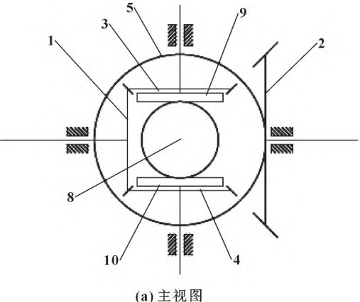
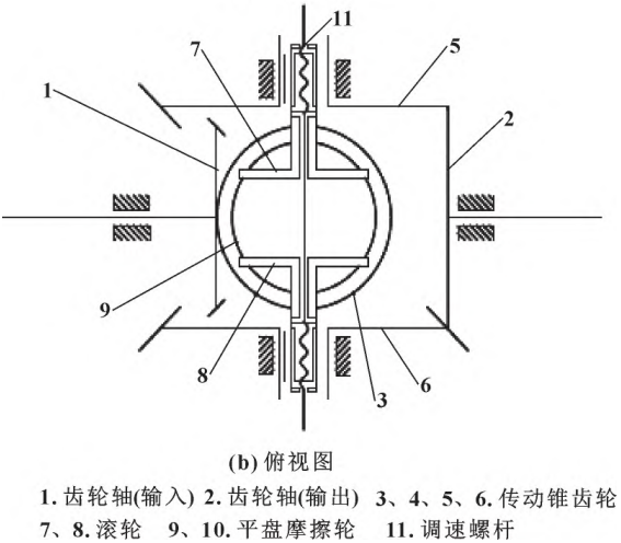
Figure 1 Principle of the new continuously variable transmission
The design in this paper adopts a symmetrical structure, with bevel gears 3 and 4 symmetrical up and down on the input-output axis. Bevel gears 5 and 6 are symmetrical on the axis left and right, rollers 7 and 8 are symmetrical on the axis left and right, and flat disc friction wheels 9 and 10 Regarding the symmetry of the axis up and down, it is spatially equivalent to flat disc friction wheels 9 and 10, with rollers 7 and 8 sandwiched in the middle. Friction wheels 9 and 10 are fixed coaxially with bevel gears 3 and 4 and rotate together. Rollers 7 and 8 are connected to bevel gears 5 and 6 by guide keys and can be ranged along their axis Axial motion. Gear shaft 1 meshes with bevel gears 3 and 4 on both sides, and gear shaft 2 engages with bevel gears 5 and 6 at the same time, symmetrically.
The power is transmitted to the input gear shaft 1 through the input shaft, and the power is transmitted by the meshing transmission of the bevel gear, and the power is shunted to the bevel gears 3 and 4, and the small end faces of the bevel gears 3 and 4 have solidly connected flat discs 9 and 10 respectively, and rotate in the same direction as bevel gears 3 and 4, and rollers 7 and 8 are pressed flat respectively
On discs 9 and 10, friction transmission is formed, and the power is transmitted to bevel gear 5 and bevel gear 6 through rollers 7 and 8, respectively, and then transmitted through bevel gear transmission to transmit the power flow to bevel gear 2 output. Rollers 7 and 8 can move along the axial direction of bevel gears 5 and 6, respectively, when rollers 7 and 8 are min
When not moving to the outside, the output speed will increase continuously and linearly, and when the roller moves inside, the output speed will continue to decrease, so as to achieve stepless variable speed transmission.
2 Slip rate calculation
2.1 Nominal gear ratio
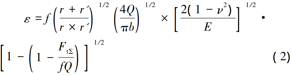
New bevel-to-roller flat disc continuously variable transmission nominal gear ratio
As follows:
Where: z1, z3, z2, z5 are the number of teeth of bevel gears 1, 3, 2, and 5, respectively; n1 is the flat disk speed, n2 is the roller speed; r is the radius of rollers 7, 8; l is the distance from the contact point between the roller and the flat disc to the center of the flat disc, and the size of l can be changed by the speed regulating mechanism to achieve stepless speed change.
2.2 Elastic sliding
Elastic sliding is mainly due to the friction contact point under pressure material elastic deformation of the sliding generated, roller and flat disc will form an oval contact area at the contact point and produce sliding when working, transmission accuracy will be affected, directly affect the transmission ratio. In the friction wheel drive train In the system, elastic slip is unavoidable, so when calculating the gear ratio
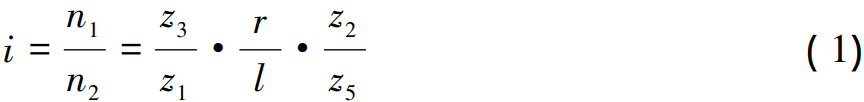
Elastic slip needs to be analyzed and the elastic slip rate is approximated The formula is as follows .
Where: ε is the elastic slip rate; r’ is the arc radius of the roller edge; E is the modulus of elasticity; ν is the Poisson’s ratio; FtΣ is the tangential resultant force of the contact surface; f is the friction factor; Q is the compression force of the contact area; b is the contact ellipse minor axis radius.
2.3 Geometric sliding
The sliding caused by the change of the geometric relationship between the main and driven wheels during the friction transmission process is called geometric sliding, as shown in Figure 2. When there is no load, the pure rolling point is the midpoint O of the contact zone, and when the load is transferred, the pure rolling point is offset from O to C, and the input angular velocity ω1 of the flat disk is set unchanged, and the actual output angular velocity of the scroll wheel is lower than the theoretical angular velocity ω2 due to the influence of sliding. The distance m between O and C points is called the node of fsetvolume, which is desirable when simplifying calculations:
Where: Kn is the transmission reliability factor.
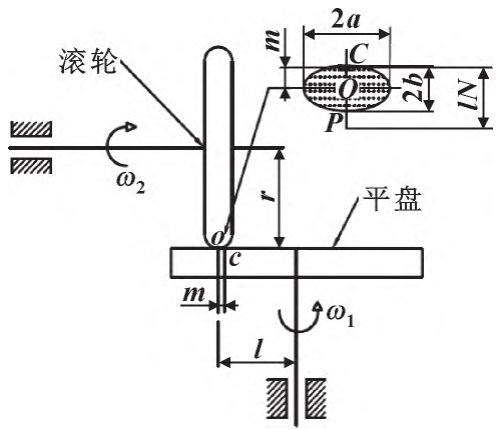
Figure 2 Slide rate analysis diagram
Contact ellipse major axis radius a and minor axis radius b are calculated as follows:
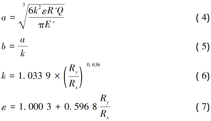
Where: Ry and Rx are the equivalent curvature radii of the roller and flat disc in the contact region, respectively; E’ is the equivalent modulus of elasticity:
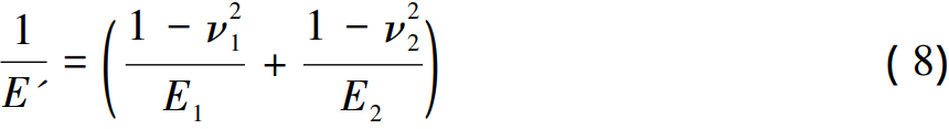
ν1 and ν2 are Poisson’s ratios of roller and flat disc materials, respectively; E1 and E2 are the modulus of elasticity, respectively; k is the ellipticity of the contact zone; ε is an approximation of elliptic integrals of the first kind; R’ is the equivalent radius of curvature. 4 Correction gear ratio Due to the influence of geometric sliding and elastic sliding, the nominal transmission ratio calculation of continuously variable transmission is inaccurate, and it needs to be corrected and repaired The positive rear transmission is as follows:
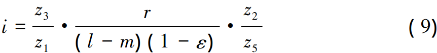
It is not difficult to see from Equation ( 9) that the actual gear ratio after correction will be slightly larger than the nominal gear ratio, and the larger the load, the higher the sliding rate, and the actual gear ratio will also increase.
3 Power loss and contact friction efficiency calculation
The vast majority of the power loss of continuously variable transmissions is frictional power loss, so only friction power loss and friction transmission efficiency are analyzed. Set any point A(x,y) in the contact zone to rub the contact zone The power loss differential expression is

vs( x,y ) is the sliding speed at any point in the contact zone:

Where: d is the distance from point A to pure scroll point C:

Finishing the above equation yields a frictional power loss of a single contact area of

Where: σmax is the maximum contact compressive stress:

Since the flat disc and roller designed in the text have 4 symmetrical contact points, the total frictional power loss Ps is

As shown in Figure 2, both the pure rolling point and the effective circumferential force action point are offset when subjected to load, and the offsets of the two are different, in fact, the effective circumferential force does not act on the pure rolling point C, but on the point P from the point C lN, simplifying the calculation:

Combining the sliding rate and the geometric relationship of each action point, the efficiency of frictional contact can be obtained:

The new bevel-roller flat disc continuously variable transmission has been calculated to have a frictional contact efficiency of more than 90%.
4 Temperature field analysis
The roller and flat disc will produce relative sliding when friction is driven, resulting in frictional heat, rising temperature and affecting the service life. Therefore, it is necessary to study the frictional heat generation and temperature field of the roller and flat disk, and the calculation formula of the frictional heat flow is as follows:

where q: q is the frictional heat flux; vs is the relative sliding speed; p is the contact compressive stress:

If the materials of the two contact parts are different, the heat distribution coefficient needs to be introduced, because the roller and flat disc materials in the text are the same, the heat is evenly distributed, and the heat distribution coefficient is 0. 5. If the loss will be at the contact point of the flat plate and the roller The heat flow into the rotation is taken as the average of the rotation cycle, and the average frictional heat flow in the rotation cycle can be expressed as respectively

Where: v1 and v2 are the line speeds of the roller and flat contact areas, respectively. The analysis selection parameters are shown in Table 1.
Table 1 Analysis parameter settings
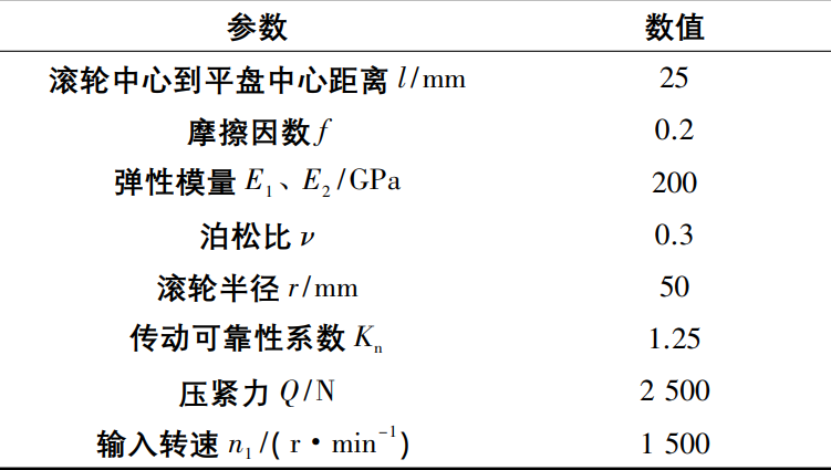
Due to the different relative sliding velocities of the points in the elliptical shape of the contact zone, the calculated frictional heat flux is also different. The maximum sliding speed is about 300 mm/s, the sliding speed at point O is about 135 mm/s, and the average sliding speed is about 200 mm/s to calculate the friction heat flow q1 ≈ 150kW/m2,q2≈75 kW/m2。
4.2 Emulation settings
Simulation analysis in ANSYS software, rollers and flat discs frictional contact, rollers as contact geometry, flat disks as target geometry. The calculated frictional heat flux is applied as a boundary condition to the contact area divided by the roller and flat disc, and the convective heat transfer coefficient is applied to the whole. This is shown in Figure 3.
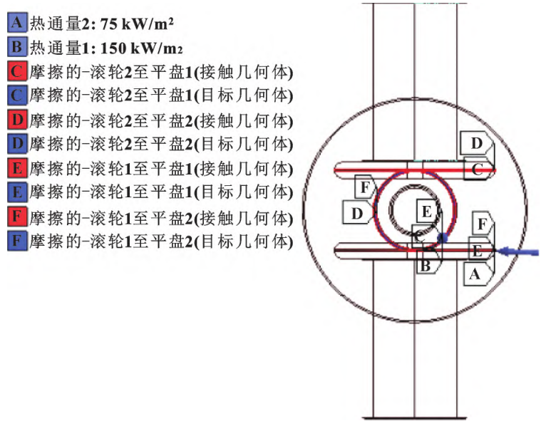
Figure 3 Boundary Conditions
The grid element type is solid227, tetrahedral division method, Slow transition, smoothing level is high. In order to further exclude the influence of mesh on the calculation results, the number of meshes is gradually increased, and the mesh size of the contact zone is gradually reduced from 1 mm, and solved sequentially, when the mesh size of the contact zone is less than 0. Continuing to reduce the mesh size at 7 mm yields a very small variation of less than 1%. Finally, select the mesh size as 0. 5mm, the mesh effect is shown in Figure 4, the number of nodes is 1 749 730, the number of cells is 1 232 666, and the average quality factor is 0. 817 5, with an average aspect ratio of 1. 91。
Figure 4 Meshing
4.3 Temperature field simulation results
The ambient temperature is 22 °C, and the convective heat transfer coefficient is 25 W/ (m2·°C) under the condition of natural convection of air. Initial substep 250, minimum substep 200, maximum substep 1 000 Opening time credit, simulation operation At row 1 800 s, the temperature result stabilizes, as shown in Figure 5.
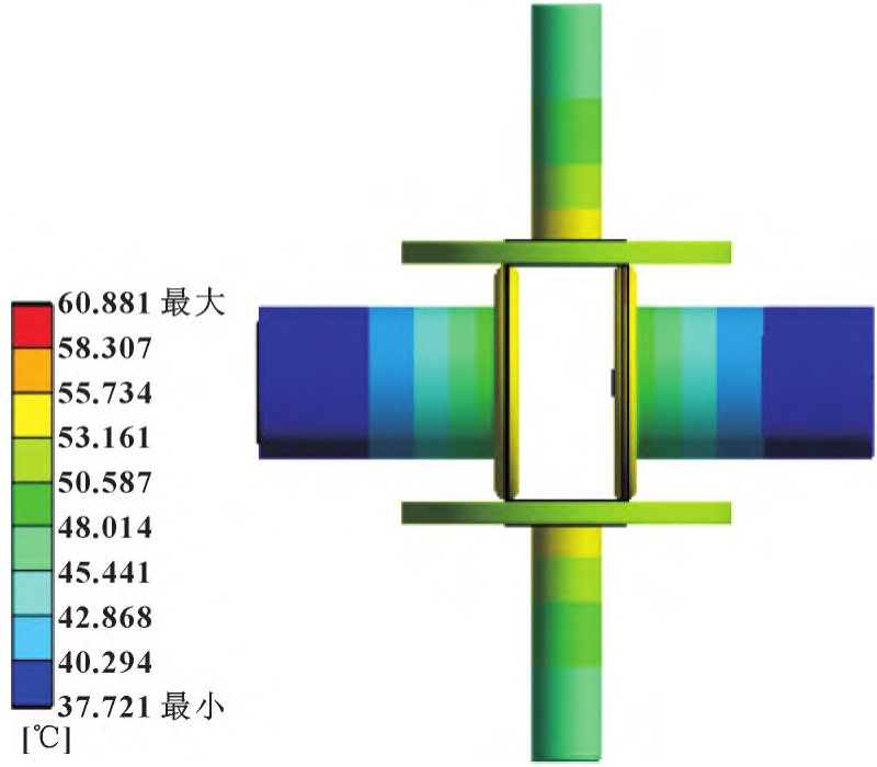
Figure 5 Temperature field during natural convection of air at 1 500 r/min
As shown in Figure 5, the maximum temperature of the overall structure is 60. 881 °C, located in the contact zone of the roller and flat disk, the temperature gradually decreases from the contact zone to the non-contact zone, and the overall temperature of the flat disc is higher than the overall temperature of the roller.
Input speed n1 is one of the important factors affecting heat flux, input speed and frictional heat flow are approximately proportional, doubling the input speed n1, sliding speed and frictional heat flux and other proportions increase. All other things remain the same, and the simulation results are shown in Figure 6 at a speed of 3 000 r/min.

Figure 6 Temperature field during natural convection of air at 3 000 r/min
As shown in Figure 6, the temperature of both the rollers and the flat disc increases with the increase of the rotational speed, reaching a maximum temperature of 99. At 75 °C, and the temperature field distribution gradient under different speed conditions is roughly the same, the greater the frictional heat flux, the greater the temperature rise, but the two are not directly proportional. At a speed of 3 000 r/min, in order to simulate the temperature field under air-cooled conditions, the convective heat transfer coefficient is increased to gas forced convection
( The convective heat transfer coefficient is 200 W/ (m2·°C), and the simulation results are shown in Figure 7.

Figure 7 Temperature field at forced convection of air at 3 000 r/min
As shown in Figure 7, under air-cooled conditions, the rollers and flat discs can be cooled relatively adequately, with a temperature drop of more than 50% and a maximum temperature of less than 44 °C. New bevel gear-roller flat disc continuously variable transmission
The friction temperature rise is within the scope of the design permit, and the design scheme is feasible.
5 Conclusion
1) Speed is one of the important factors affecting the friction heating of rollers and flat discs, and the temperature of rollers and flat discs will rise with the increase of speed, the main reason is that the increase of speed increases the sliding speed
More frictional heat.
( 2) With the increase of the compressive force, the pure rolling point offset m and the effective circumferential force offset lN will increase, the frictional power loss will increase, and the friction efficiency will decrease. At the same time, the compressive force affects the frictional heat flux
The sound is loud. With the increase of pressing force, not only the sliding speed will increase, generating more frictional heat, but also increase the contact area, and the frictional heating area is larger, so the impact on temperature rise is more obvious.
( 3) The friction efficiency of the new bevel gear-roller flat disc continuously variable transmission is high, which can reach more than 90%, the friction heat generation is relatively small, the temperature rise is lower, and it is greatly improved than the existing friction type continuously variable transmission, which meets the design requirements.