
I have concentrated my investigation on the precision forging of a straight bevel gear because this component is widely used in vehicles, machine tools, ships, and many other engineering systems. A straight bevel gear transmits motion and torque between intersecting axes, and its most critical feature is the tooth profile. Traditional gear cutting can produce accurate teeth, but it removes material, interrupts the grain flow, wastes raw material, and often requires expensive finishing operations. For this reason, the rapid production of high-quality gears by precision forging has become a global trend. In my work, I treat the straight bevel gear as a forged component whose final quality depends strongly on the design of the pre-forging tooth. A single-stage precision forging operation is usually insufficient for a straight bevel gear with a demanding tooth shape. Therefore, composite routes such as hot pre-forging plus cold final forging, hot pre-forging plus warm final forging, and warm pre-forging plus cold final forging are often used. These routes require at least two steps, namely pre-forging and final forging, to obtain a satisfactory tooth profile. The pre-forging step improves metal fill during final forging, prevents folds and cracks, and helps extend die life. Consequently, the design of a reasonable pre-forging shape, especially a reasonable pre-forging tooth, is of great importance for the final quality of a straight bevel gear.
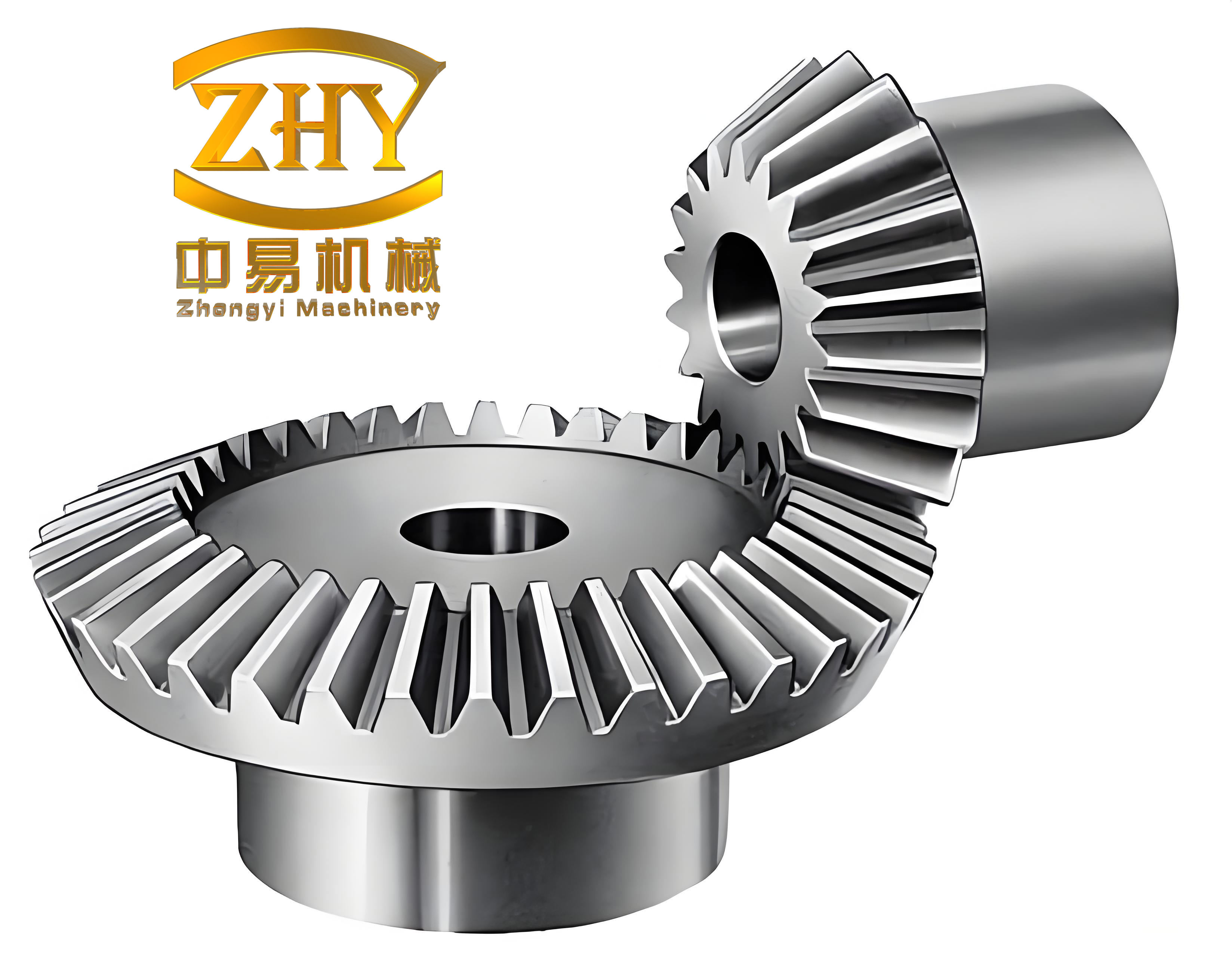
I apply the central shunt method, also described as a divided-flow precision forging process, to a straight bevel gear. The principle of this method is that a punch with a central boss forms a shunt zone at the center of the billet end face during pre-forging. This shunt zone is a controlled volume of empty space. At the same time, the boss of the punch forces material outward toward the tooth cavity. During final forging, the pre-forged shunt zone allows material to continue filling the tooth cavity, which improves the final forming quality of the straight bevel gear. The object of my study is a straight bevel gear formed by a two-step route: pre-forging and final forging. I summarize my process route in Table 1.
| Step | Operation | Purpose | Critical Control |
|---|---|---|---|
| 1 | Precision blanking | Obtain a billet with accurate volume | Mass and volume tolerance |
| 2 | Turning or grinding of outer diameter | Remove surface defects and scale | Surface cleanliness and diameter |
| 3 | Low-oxidation or atmosphere-controlled heating | Raise billet temperature uniformly | Temperature uniformity and scale control |
| 4 | Pre-forging | Form a trapezoidal nonstandard tooth and a central shunt zone | Shunt volume and tooth fill |
| 5 | Final forging | Form the standard involute tooth of the straight bevel gear | Tooth profile, flash, and folding |
| 6 | Cold trimming | Remove flash | Edge quality and dimensional accuracy |
| 7 | Heat treatment | Improve mechanical properties | Hardness and microstructure |
| 8 | Subsequent machining | Finish functional surfaces | Final tolerance |
For a straight bevel gear forged by the central shunt method, the volume distribution must be controlled carefully. I use the following volume relation for the billet, pre-forging, and final forging:
$$ V_{billet} = V_{pre} + V_{flash,pre} + V_{loss,pre} $$
$$ V_{pre} = V_{final} + V_{shunt} + V_{flash,final} + V_{loss,final} $$
Here, \(V_{billet}\) is the initial billet volume, \(V_{pre}\) is the pre-forging volume, \(V_{final}\) is the final forging volume, \(V_{shunt}\) is the volume of the central shunt zone, and \(V_{flash}\) represents the flash volume. The shunt zone is usually created by a circular or annular boss on the upper punch. I describe its basic area as
$$ A_{shunt} = \pi r_{shunt}^{2} $$
where \(r_{shunt}\) is the effective radius of the shunt zone. The height and shape of the boss determine how strongly the material is driven toward the tooth cavity. If the shunt volume is too small, the tooth cavity of the straight bevel gear may not fill completely. If the shunt volume is too large, excessive material may flow into the flash and the forging load may increase. Therefore, I treat the shunt volume as one of the most important process variables.
Before designing my trapezoidal nonstandard pre-forging tooth, I reviewed the common approaches for pre-forging tooth design. The most direct approach is to use a standard tooth profile, that is, a standard involute tooth profile. The greatest advantage of a standard pre-forging tooth is that the pre-forging is very close to the final forging shape, so the final deformation amount is greatly reduced. However, a standard pre-forging tooth also has serious disadvantages. Because the pre-forging tooth is close to the final tooth, the pre-forging die cavity is almost as complex as the final forging die cavity. This increases die manufacturing cost. More importantly, a standard pre-forging tooth can lead to folding, poor fill at the large end, and high final forging load. In some studies, the pre-forging tooth height was increased to make the final tooth form by upsetting. The result was that the tooth did not upset simultaneously along the whole face width. Instead, deformation progressed gradually from the small end to the large end. This caused folding on the tooth surface and made the large end of the straight bevel gear tooth incomplete. In other studies, the standard pre-forging tooth was offset outward by a finishing allowance, and the root circle was offset inward to keep the volume constant. The final forging simulation showed that the maximum forming force increased with the finishing allowance, and folding appeared at the tooth root. When the finishing allowance was reduced, the folding decreased but did not disappear completely. A nonstandard pre-forging tooth with a larger finishing allowance at the middle of the tooth face solved the folding problem in cold finishing. These findings led me to conclude that a nonstandard pre-forging tooth can be superior to a standard pre-forging tooth for a straight bevel gear.
In my view, if the final forging quality can be guaranteed, the pre-forging tooth should be as simple as possible. A simpler pre-forging tooth reduces the machining difficulty and manufacturing cost of the pre-forging die. I therefore selected a trapezoidal nonstandard tooth as the pre-forging tooth shape. I first considered a full-height trapezoidal tooth. However, a full-height trapezoidal tooth makes the pre-forging die groove narrow and deep, which makes metal filling difficult during pre-forging. I also considered the tooth-top shunt process. Research has shown that applying a tooth-top shunt to gear forming can effectively solve incomplete filling at tooth corner edges and can reduce the forming load. Therefore, I finally adopted a trapezoidal tooth that is slightly larger than one-half of the final tooth height. This design ensures that a shunt space exists both at the tooth face and at the tooth top during final forging.
For the straight bevel gear geometry, I use the standard involute relations as the reference for the final tooth. The base radius is
$$ r_b = r \cos \alpha $$
where \(r\) is the reference radius and \(\alpha\) is the pressure angle. The involute angle is
$$ \theta = \tan \alpha – \alpha $$
The involute profile can be written parametrically as
$$ x = r_b \left( \cos \theta + \theta \sin \theta \right) $$
$$ y = r_b \left( \sin \theta – \theta \cos \theta \right) $$
The module and reference diameter are related by
$$ d = m z $$
where \(m\) is the module and \(z\) is the number of teeth. For a straight bevel gear, the tooth thickness and tooth height vary along the face width, so the pre-forging tooth must also vary along the face width. The reference geometry I used for the straight bevel gear is summarized in Table 2.
| Parameter | Symbol | Reference Value | Unit |
|---|---|---|---|
| Small-end diameter | \(d_s\) | 38.00 | mm |
| Reference diameter 1 | \(d_1\) | 49.09 | mm |
| Reference diameter 2 | \(d_2\) | 55.00 | mm |
| Large-end diameter | \(d_l\) | 59.92 | mm |
| Face width | \(b\) | 15.20 | mm |
| Pitch cone angle | \(\delta\) | 24.00 | deg |
| Tip cone angle | \(\delta_a\) | 29.00 | deg |
| Root cone angle | \(\delta_f\) | 26.50 | deg |
| Outer cone distance | \(R\) | 61.66 | mm |
| Tooth height at large end | \(h_l\) | 22.28 | mm |
| Tooth height at small end | \(h_s\) | 21.00 | mm |
| Pressure angle | \(\alpha\) | 20.00 | deg |
The trapezoidal pre-forging tooth is defined by its height, top width, bottom width, and draft angle. I write the trapezoidal area as
$$ A_{pre} = \frac{1}{2} \left( w_t + w_b \right) h_{pre} $$
where \(w_t\) is the top width, \(w_b\) is the bottom width, and \(h_{pre}\) is the pre-forging tooth height. The pre-forging tooth height is related to the final tooth height by
$$ h_{pre} = k h_{final} $$
I selected \(k\) in the range of 0.55 to 0.65, which means that the pre-forging tooth is slightly larger than one-half of the final tooth height. This non-full-height trapezoidal tooth keeps the die groove open enough for metal flow. The draft angle of the trapezoid is
$$ \beta = \arctan \left( \frac{w_b – w_t}{2 h_{pre}} \right) $$
I found that a draft angle between 8 and 12 degrees gives a good balance between easy filling and sufficient tooth volume. The volume of the trapezoidal pre-forging tooth along the face width can be approximated by
$$ V_{tooth,pre} = n \int_{0}^{b} A_{pre}(s) \, ds $$
where \(n\) is the number of teeth and \(s\) is the coordinate along the face width. The final tooth volume is
$$ V_{tooth,final} = n \int_{0}^{b} A_{final}(s) \, ds $$
The difference between the final tooth volume and the pre-forging tooth volume creates the space that must be filled during final forging. I express this as
$$ V_{gap} = V_{tooth,final} – V_{tooth,pre} + V_{shunt} $$
This gap is not a defect. In my design, it acts as a controlled shunt space. During final forging, metal flows into this gap and fills the involute tooth cavity of the straight bevel gear. The central shunt zone from the punch boss also provides an additional volume for material redistribution. The combination of the central shunt and the trapezoidal tooth gap produces a favorable flow pattern. I list the main design variables of the trapezoidal pre-forging tooth in Table 3.
| Design Variable | Symbol | Selected Range | Function |
|---|---|---|---|
| Pre-forging tooth height ratio | \(k\) | 0.55 to 0.65 | Controls non-full-height trapezoid |
| Top width | \(w_t\) | Matched to final top land | Controls tooth-top gap |
| Bottom width | \(w_b\) | Matched to final root width | Controls root fill |
| Draft angle | \(\beta\) | 8 to 12 deg | Improves die filling and ejection |
| Corner radius | \(r_c\) | 0.5 to 1.0 mm | Reduces stress concentration |
| Central boss radius | \(r_{boss}\) | 5 to 15 mm | Creates shunt zone |
| Central boss height | \(h_{boss}\) | 2 to 6 mm | Drives material to tooth cavity |
After designing the trapezoidal nonstandard pre-forging tooth, I used UG software to create the pre-forging die with a trapezoidal tooth groove and the final forging die with a standard involute tooth groove. I then imported both models into DEFORM-3D for numerical simulation. The simulation parameters are given in Table 4. I used a mesh with 80,000 elements and automatic compensation to make up for volume loss caused by mesh distortion. The initial die temperature was set to 200 degrees Celsius, and the initial billet temperature was set to 800 degrees Celsius. The friction coefficient between the billet and dies was 0.25, with good lubrication. The upper die moved at 50 mm/s. The heat transfer coefficient between the billet and air was 0.02 N/(s mm degrees C), and the heat transfer coefficient between the billet and the upper and lower dies was 5 N/(s mm degrees C).
| Simulation Parameter | Value | Unit |
|---|---|---|
| Software | DEFORM-3D | — |
| Mesh element number | 80,000 | — |
| Remeshing volume compensation | Automatic | — |
| Initial die temperature | 200 | degrees C |
| Initial billet temperature | 800 | degrees C |
| Friction coefficient | 0.25 | — |
| Upper die speed | 50 | mm/s |
| Billet-air heat transfer coefficient | 0.02 | N/(s mm degrees C) |
| Billet-die heat transfer coefficient | 5 | N/(s mm degrees C) |
For the thermal and mechanical simulation, I used the following heat transfer equation:
$$ \rho c_p \frac{\partial T}{\partial t} = \nabla \cdot \left( k \nabla T \right) + \dot{q} $$
where \(\rho\) is density, \(c_p\) is specific heat, \(T\) is temperature, \(k\) is thermal conductivity, and \(\dot{q}\) is the internal heat generation rate due to plastic deformation. The friction stress at the die-billet interface is described by the Coulomb friction model:
$$ \tau = \mu p $$
where \(\tau\) is the friction shear stress, \(\mu\) is the friction coefficient, and \(p\) is the normal contact pressure. The forging force is obtained by integrating the normal and shear stresses over the contact area:
$$ F = \int_{A} \sigma_n \, dA + \int_{A} \tau \, dA $$
The effective strain and effective strain rate are defined as
$$ \bar{\varepsilon} = \sqrt{\frac{2}{3} \varepsilon_{ij} \varepsilon_{ij}} $$
$$ \dot{\bar{\varepsilon}} = \sqrt{\frac{2}{3} \dot{\varepsilon}_{ij} \dot{\varepsilon}_{ij}} $$
I used a thermomechanical flow stress model of the form
$$ \sigma = K \varepsilon^{n} \dot{\varepsilon}^{m} \exp \left( \frac{Q}{RT} \right) $$
where \(K\) is a material constant, \(n\) is the strain-hardening exponent, \(m\) is the strain-rate sensitivity exponent, \(Q\) is the activation energy, \(R\) is the universal gas constant, and \(T\) is the absolute temperature. This model allows the simulation to account for the combined effects of strain, strain rate, and temperature during the forging of the straight bevel gear.
During pre-forging, I observed three main filling stages. In the first stage, the punch boss began to press the billet, and the material contacted the small-end tooth top of the trapezoidal groove. In the second stage, the material gradually contacted the entire tooth top and underwent upsetting deformation. The billet became a conical frustum and began to fill the upper die cavity. In the third stage, the material flowed radially into the trapezoidal tooth groove, continued toward the small-end tooth top and large-end tooth top, and finally filled the entire trapezoidal tooth. Because the trapezoidal groove is simple and open, the pre-forging fill was easy to achieve. I obtained a complete trapezoidal pre-forging tooth without narrow deep corners that could block flow.
During final forging, the pre-forged central recess acted as a shunt zone. In addition, the gap between the trapezoidal pre-forging tooth and the involute final tooth groove acted as a second shunt space. Under the downward motion of the upper die, metal flowed into the gap between the pre-forging tooth and the final tooth groove. The flow was intense and continuous. The tooth cavity of the straight bevel gear filled rapidly. In particular, the tooth-top corner edges filled completely. I did not observe folding or cracking. The final forging tooth surface was smooth and full, and the tooth profile was symmetric. The velocity field showed that the metal flowed toward the tooth top and along the tooth flank in a controlled manner. The central shunt zone reduced the resistance to flow and allowed material to be redistributed from the center to the tooth cavity.
I summarize the comparison between a standard pre-forging tooth and my trapezoidal nonstandard pre-forging tooth in Table 5. The standard involute pre-forging tooth is close to the final shape and can reduce final deformation, but it requires a complex pre-forging die and has a higher risk of folding. My trapezoidal nonstandard tooth is simpler, easier to manufacture, and provides better shunt conditions. It also reduces the maximum forming load and improves the final fill of the straight bevel gear.
| Aspect | Standard Involute Pre-forging Tooth | Trapezoidal Nonstandard Pre-forging Tooth |
|---|---|---|
| Die cavity complexity | High | Low |
| Die manufacturing cost | High | Lower |
| Tooth fill during pre-forging | Difficult in narrow corners | Easy because groove is open |
| Shunt space | Limited | Enhanced by central boss and tooth gap |
| Folding risk | High at root or flank | Low |
| Final forging load | High | Reduced |
| Final tooth quality | Sometimes incomplete at large end | Complete and symmetric |
| Applicability to straight bevel gear | Possible but sensitive | Favorable |
The simulation results also allowed me to evaluate the filling index. I define the filling index as
$$ \Phi = \frac{V_{filled}}{V_{cavity}} \times 100\% $$
For the trapezoidal pre-forging tooth, the pre-forging cavity filled completely, so \(\Phi_{pre} \approx 100\%\). For the final forging of the straight bevel gear, the involute tooth cavity also filled completely, so \(\Phi_{final} \approx 100\%\). This confirms that the trapezoidal nonstandard pre-forging tooth provides sufficient material and favorable flow conditions for the final tooth. I also define a shunt efficiency as
$$ \eta_{shunt} = \frac{V_{shunt,used}}{V_{shunt,total}} \times 100\% $$
A high shunt efficiency means that the central shunt zone is effectively used to fill the tooth cavity rather than merely producing flash. In my simulation, the central boss and the trapezoidal tooth gap worked together, and the shunt efficiency was high enough to ensure complete filling without excessive flash. The flash volume remained within a controllable range.
I further examined the forming load. The maximum forming load in final forging with the trapezoidal pre-forging tooth was lower than that with a standard pre-forging tooth under the same conditions. The reason is that the trapezoidal tooth reduces the contact area at the beginning of final forging and provides additional shunt volume. The flow stress also decreases because the material undergoes less redundant deformation. I express the load reduction qualitatively as
$$ F_{trap} < F_{std} $$
where \(F_{trap}\) is the maximum load with the trapezoidal pre-forging tooth and \(F_{std}\) is the maximum load with the standard pre-forging tooth. A lower load is beneficial because it reduces the required press capacity, decreases die stress, and improves die life. The die stress can be estimated by
$$ \sigma_{die} = \frac{F}{A_{contact}} $$
where \(A_{contact}\) is the contact area between the die and the billet. Since the trapezoidal design reduces the peak load, the maximum die stress is also reduced. I require that
$$ \sigma_{die} \leq [\sigma] $$
where \([\sigma]\) is the allowable stress of the die material. This condition is easier to satisfy with the trapezoidal nonstandard pre-forging tooth than with a standard pre-forging tooth.
The velocity field of the straight bevel gear during final forging showed a strong downward and radial flow pattern. The metal near the center flowed outward under the action of the punch boss. The metal near the tooth flank flowed along the involute cavity. The metal near the tooth top flowed upward into the corner regions. This flow pattern is desirable because it avoids the formation of a dead zone. A dead zone would cause incomplete filling or folding. In my simulation, the velocity vectors were continuous and the material flowed smoothly into the tooth cavity. The tooth surface was formed by a combination of upsetting and extrusion-like flow, but the flow was stable. The central shunt method therefore works well with the trapezoidal nonstandard pre-forging tooth for the straight bevel gear.
I also studied the influence of several design parameters on the final result. The height ratio \(k\) is critical. If \(k\) is too small, the pre-forging tooth is too short, and the gap between the pre-forging tooth and the final tooth groove is too large. This can cause excessive flow and may lead to flash or incomplete filling. If \(k\) is too large, the pre-forging tooth is too close to the final tooth height, and the die groove becomes deep and narrow. This increases filling difficulty and load. I found that \(k = 0.55\) to \(0.65\) gives a good balance. The draft angle \(\beta\) is also important. A small draft angle can cause the material to stick in the die groove, while a large draft angle reduces the effective tooth volume and may cause poor final tooth shape. I selected \(8^\circ\) to \(12^\circ\). The corner radius \(r_c\) should not be too small, because a sharp corner causes stress concentration and may lead to cracking. A radius of 0.5 to 1.0 mm is suitable. The central boss radius and height control the shunt volume. If the boss is too small, the shunt action is weak. If the boss is too large, the billet may be pierced or the flow may become unstable. I selected a boss radius of 5 to 15 mm and a boss height of 2 to 6 mm. These ranges are summarized in Table 6.
| Parameter | Too Small | Too Large | Selected Optimum |
|---|---|---|---|
| Height ratio \(k\) | Insufficient drive, excessive gap | Deep groove, difficult fill | 0.55 to 0.65 |
| Draft angle \(\beta\) | Sticking, poor ejection | Low tooth volume, poor final shape | 8 to 12 deg |
| Corner radius \(r_c\) | Stress concentration, cracking | Inaccurate corner geometry | 0.5 to 1.0 mm |
| Boss radius \(r_{boss}\) | Weak shunt action | Unstable flow, piercing risk | 5 to 15 mm |
| Boss height \(h_{boss}\) | Insufficient material drive | Excess flash, high load | 2 to 6 mm |
The numerical simulation confirmed that the trapezoidal nonstandard pre-forging tooth is feasible for the central shunt precision forging of a straight bevel gear. The pre-forging step produced a complete trapezoidal tooth and a central shunt recess. The final forging step produced a complete involute tooth with a smooth surface and symmetric profile. No folding or cracking was observed. The forming load was lower than that of the standard pre-forging tooth. The die cavity for the trapezoidal pre-forging tooth is much simpler than the involute final forging cavity, so the pre-forging die is easier to manufacture and less expensive. This is important because the pre-forging step is not the final step. The pre-forging tooth does not need to match the final tooth exactly. It only needs to provide a favorable distribution of material and a favorable flow path for final forging. By simplifying the pre-forging tooth, I reduce cost without sacrificing final quality.
In my analysis, the central shunt method has several advantages for the straight bevel gear. First, the central shunt zone reduces the resistance to material flow in the tooth cavity. Second, the punch boss actively drives material toward the tooth cavity. Third, the shunt zone reduces the peak forming load. Fourth, the process improves tooth filling at the tooth top and corner edges. Fifth, the process reduces the risk of folding and cracking. Sixth, the process can be combined with a simple trapezoidal pre-forging tooth, which lowers die cost. These advantages are summarized in Table 7.
| Advantage | Mechanism | Effect on Straight Bevel Gear |
|---|---|---|
| Reduced flow resistance | Central shunt volume provides space for material redistribution | Easier tooth cavity filling |
| Active material drive | Punch boss forces metal outward | Better fill at tooth flank and top |
| Lower forming load | Smaller contact area and favorable flow | Less press capacity required |
| Improved corner filling | Tooth-top gap acts as local shunt | Complete tooth-top edges |
| Lower defect risk | Smooth velocity field and no dead zone | No folding or cracking |
| Lower die cost | Simple trapezoidal pre-forging groove | Cheaper pre-forging die |
I also considered the limitations of my approach. The trapezoidal nonstandard pre-forging tooth must be optimized for each straight bevel gear geometry. The optimal height ratio, draft angle, and shunt volume depend on the module, tooth count, face width, and cone angle. A design that works for one straight bevel gear may not work for another without adjustment. The simulation also depends on the accuracy of the flow stress model and the friction model. If the friction coefficient is different in production, the flow pattern may change. For this reason, I recommend that the simulation results be validated by physical trials. The die temperature and billet temperature must also be controlled carefully. If the billet temperature is too low, the flow stress increases and filling becomes difficult. If the billet temperature is too high, oxidation and grain growth may occur. I used 800 degrees Celsius for the billet and 200 degrees Celsius for the dies, which gave good simulation results. In production, these temperatures should be maintained within a narrow range.
For the straight bevel gear, the final tooth profile is a standard involute. The pre-forging tooth is a trapezoid. The transition from trapezoid to involute occurs during final forging. The amount of deformation in final forging is moderate. It is large enough to refine the microstructure and ensure good tooth properties, but not so large that it causes folding or excessive load. I believe this balance is the main reason for the success of the trapezoidal nonstandard pre-forging tooth. A standard pre-forging tooth would reduce the final deformation too much and would make the pre-forging die too complex. A full-height trapezoidal tooth would make the pre-forging die too deep. The non-full-height trapezoidal tooth avoids both problems. It provides sufficient pre-forging volume, a simple die cavity, and a favorable shunt space.
The velocity field during final forging can be interpreted using the following relation between the material velocity and the die velocity:
$$ \mathbf{v} = \mathbf{v}_{die} + \mathbf{v}_{flow} $$
where \(\mathbf{v}\) is the total velocity of a material point, \(\mathbf{v}_{die}\) is the velocity of the die surface, and \(\mathbf{v}_{flow}\) is the relative flow velocity. In my simulation, \(\mathbf{v}_{flow}\) was directed toward the unfilled tooth regions. The central shunt zone allowed the relative flow to develop without excessive pressure. The strain rate in the tooth cavity was high near the tooth top and lower near the tooth root. This distribution helped fill the tooth top without overloading the root. The effective strain distribution was also more uniform than in the standard pre-forging case. A more uniform effective strain is beneficial because it reduces the risk of internal defects and improves the mechanical properties of the forged straight bevel gear.
I can also express the material incompressibility condition as
$$ \nabla \cdot \mathbf{v} = 0 $$
This condition is satisfied in the simulation because the material is treated as a dense, incompressible plastic body. The volume change due to elastic deformation is neglected. The automatic remeshing and volume compensation in DEFORM-3D help maintain the volume during large deformation. The mesh quality was checked throughout the simulation. In regions of high strain, the mesh was refined automatically. This ensured that the tooth profile was captured accurately. The simulation results were stable, and no numerical divergence occurred. The final forging load curve increased smoothly and then decreased as the tooth cavity filled. The maximum load occurred near the end of the filling stage. The trapezoidal pre-forging tooth reduced the maximum load compared with the standard pre-forging tooth.
In conclusion, my study shows that the design of the pre-forging tooth is of great significance for improving the fill behavior of a straight bevel gear during precision forging. A nonstandard pre-forging tooth has advantages over a standard pre-forging tooth in improving gear forming quality. For the central shunt precision forging of a straight bevel gear, a simple non-full-height trapezoidal pre-forging tooth is feasible. It ensures complete forming of the final forging. Because the pre-forging step is not the final step, the pre-forging tooth should be simplified as much as possible while still guaranteeing the final forging quality. This reduces the machining difficulty and manufacturing cost of the pre-forging die. The trapezoidal nonstandard pre-forging tooth provides a central shunt zone and a tooth-top shunt space, which together improve metal flow and reduce the forming load. The final forging of the straight bevel gear is complete, smooth, and symmetric. No folding or cracking occurs. The simulation results confirm the feasibility of the proposed design.
For future work, I would optimize the trapezoidal pre-forging tooth using a parametric model and a multi-objective optimization algorithm. The objectives would include minimizing the maximum forming load, maximizing the filling index, reducing the effective strain variance, and minimizing the flash volume. The design variables would include the height ratio, draft angle, corner radius, boss radius, and boss height. I would also include the die stress as a constraint. The optimization problem can be written as
$$ \min_{\mathbf{x}} \; f(\mathbf{x}) = \left[ F_{max}, \; -\Phi, \; \sigma_{\bar{\varepsilon}}, \; V_{flash} \right] $$
subject to
$$ \sigma_{die} \leq [\sigma] $$
$$ \Phi \geq 99\% $$
$$ h_{pre} = k h_{final}, \quad 0.55 \leq k \leq 0.65 $$
$$ 8^\circ \leq \beta \leq 12^\circ $$
where \(\mathbf{x}\) is the vector of design variables. This optimization would further improve the process for the straight bevel gear. I would also perform physical forging trials to validate the simulation results. The trials would measure the final tooth profile, surface quality, forming load, and die wear. The measured data would be compared with the simulated data. Any discrepancy would be used to refine the friction model, the heat transfer model, and the flow stress model. The validated model could then be used to design pre-forging teeth for other straight bevel gear sizes and other gear types.
I believe that the central shunt method combined with a trapezoidal nonstandard pre-forging tooth is a practical and efficient route for the precision forging of a straight bevel gear. It reduces die cost, improves tooth filling, lowers forming load, and avoids folding. The process is especially suitable for high-volume production because the pre-forging die is simple and the final forging die produces an accurate involute tooth. The use of DEFORM-3D simulation allows the designer to evaluate the process before committing to expensive tooling. By studying the velocity field, effective strain, temperature field, and load curve, the designer can choose the optimal pre-forging tooth shape. My results show that a non-full-height trapezoidal tooth is a strong candidate for the pre-forging of a straight bevel gear. The design is simple, robust, and effective. It provides a clear path for the automotive, machine tool, and shipbuilding industries to produce high-quality straight bevel gears by precision forging.