
In my extensive research into precision forming technologies, warm extrusion has consistently emerged as a superior method for manufacturing high-strength, net-shape components like spur and pinion gears. The process, conducted at temperatures between room temperature and recrystallization, uniquely balances the advantages of cold forging—such as excellent dimensional accuracy and surface finish—with the reduced forming forces and increased material ductility characteristic of hot forging. This makes it particularly suitable for challenging materials and complex geometries. The successful production of a defect-free spur and pinion gear via warm extrusion is not trivial; it is a delicate interplay of die design, lubrication, thermal management, and process parameters. Through years of simulation and analysis, I have developed a framework for understanding and optimizing this process, with a particular focus on how geometric factors like tooth count and module influence metal flow and final quality.
The heart of the warm extrusion process for a spur and pinion gear lies in the deformation mechanics within the die cavity. When a cylindrical billet is pressed into a die containing the negative impression of the gear, the material undergoes severe plastic deformation. The fundamental relationship governing this is the flow stress, which is highly sensitive to strain, strain rate, and temperature during warm forming. A commonly used constitutive model to describe this behavior is the Hensel-Spittel equation:
$$ \sigma_f = A e^{m_1 T} \varepsilon^{m_2} \dot{\varepsilon}^{m_3} e^{\frac{m_4}{\varepsilon}} (1 + \varepsilon)^{m_5 T} e^{m_6 \varepsilon} \dot{\varepsilon}^{m_7 T} T^{m_8} $$
where $\sigma_f$ is the flow stress, $\varepsilon$ is the strain, $\dot{\varepsilon}$ is the strain rate, $T$ is the temperature, and $A, m_1…m_8$ are material constants. For gear extrusion, the strain is not uniform. The teeth regions experience significantly higher strains than the core. The extrusion ratio, a key parameter, is defined for this process not in a simple area reduction sense but can be conceptualized as the ratio of the billet cross-sectional area to the total projected area of the gear face including the teeth interstices. A higher effective ratio implies greater difficulty in filling the tooth tips.
My investigation centers on a critical die design element: the relationship between the number of teeth (which inversely affects the module for a constant pitch diameter) and the resulting forming defects. I systematically analyzed gears with different tooth counts, keeping the pitch diameter and billet diameter constant. The primary variable was the module, $m$, calculated as $m = d_p / z$, where $d_p$ is the pitch diameter and $z$ is the number of teeth. A higher tooth count means a smaller module and finer teeth. The following table summarizes the core geometric and expected deformation characteristics for three cases I simulated.
| Case ID | Number of Teeth (z) | Module (m) | Tooth Height (approx.) | Theoretical Deformation Severity |
|---|---|---|---|---|
| A | 17 | Large | Tall | High |
| B | 23 | Medium | Medium | Medium |
| C | 37 | Small | Short | Low |
The finite element method (FEM) is an indispensable tool for visualizing and quantifying the complex, non-steady state metal flow during spur and pinion gear extrusion. I employ a coupled thermo-mechanical analysis to account for deformation heating and heat transfer to the dies. The simulation model incorporates several critical physical phenomena:
- Contact and Friction: A shear friction model, $\tau = m_k \cdot \sigma_y / \sqrt{3}$, is typically used, where $\tau$ is the frictional shear stress, $m_k$ is the friction factor (ranging from 0.1 for excellent lubrication to 0.7 for sticking), and $\sigma_y$ is the current yield stress of the material.
- Material Model: As mentioned, a temperature and strain-rate dependent plasticity model is essential.
- Damage Initiation: Criteria like the Cockcroft & Latham or Oyane ductile fracture criteria are monitored to predict potential cracking, especially at tooth tips: $$ \text{Cockcroft-Latham: } \int_0^{\varepsilon_f} \frac{\sigma^*}{\bar{\sigma}} d\bar{\varepsilon} = C_1 $$ where $\sigma^*$ is the maximum principal stress, $\bar{\sigma}$ is the effective stress, and $\bar{\varepsilon}$ is the effective strain.
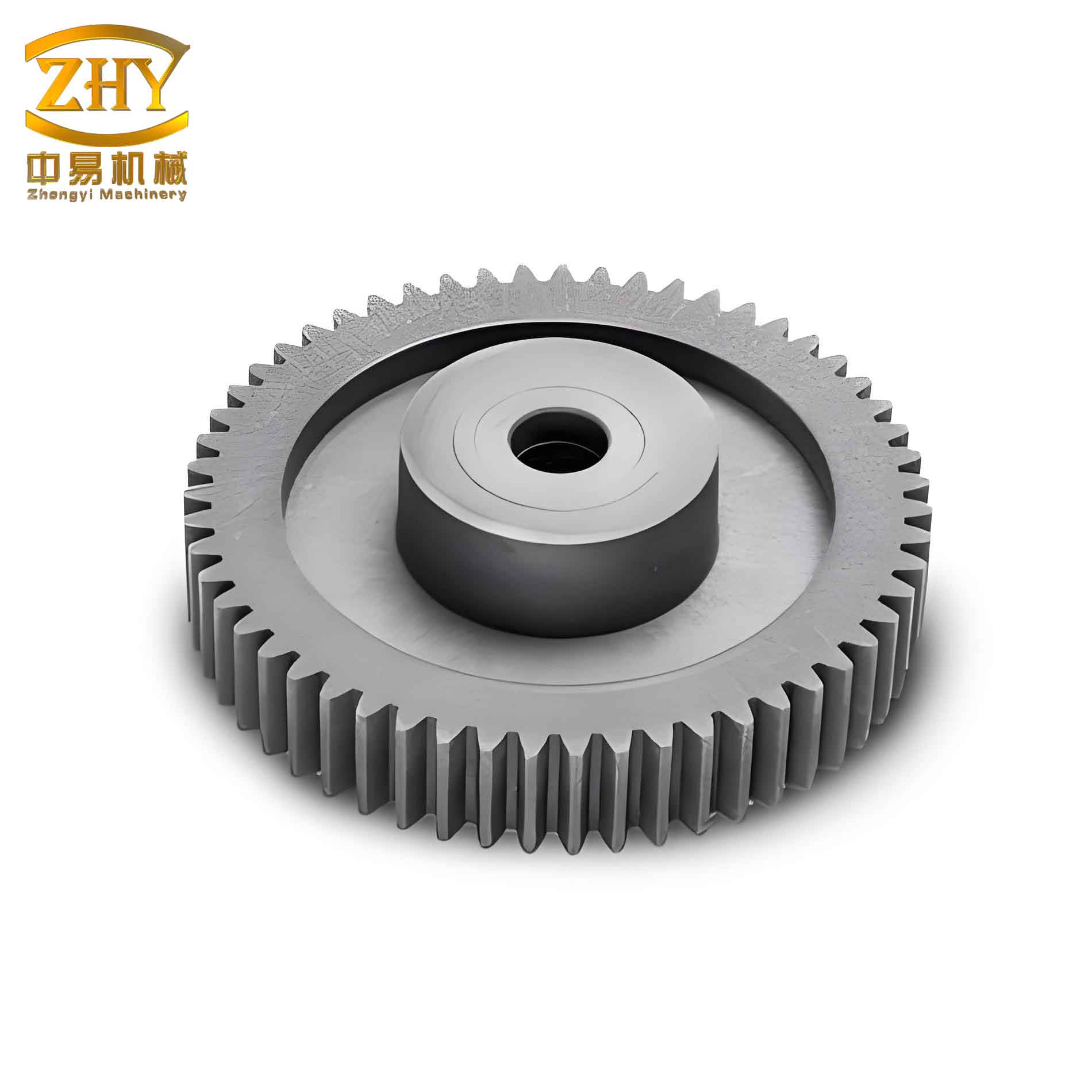
The simulation results for the three gear cases revealed a clear and consistent trend linking tooth geometry to defect formation. For the fine-pitch, high tooth-count spur and pinion gear (Case C, z=37), the metal flow was characterized by a dominant “bridging” or “shunting” effect. The numerous, closely spaced die teeth act as multiple obstructions, splitting the material flow into many small streams. The deformation degree in the tooth region is relatively low. The velocity field analysis shows that the material primarily flows axially downward, with only a minimal lateral component pushing metal into the tooth cavities. This results in severe underfilling at the tooth tips. Furthermore, the high surface-area-to-volume ratio of the teeth increases the influence of friction, which can exceed the local yield strength of the under-pressure material, leading to surface tearing or “fold-over” defects at the tooth corners. The extruded gear head often appears relatively flat.
Conversely, for the coarse-pitch, low tooth-count spur and pinion gear (Case A, z=17), the deformation degree is significantly higher. The die teeth are fewer and taller, creating larger cavities to fill. The velocity field is markedly different. A substantial portion of the material is diverted radially outward into the tooth spaces. The higher strain energizes the metal flow, promoting better filling of the tooth tips. However, this improved fill comes with other challenges. The velocity differential between the material at the center of the gear and that near the outer diameter/tooth roots becomes pronounced. This non-uniform flow leads to two distinct defects: an inward concavity (sinking) at the center of the extruded gear face, and a “bulging” or convex profile on the flanks of the leading-edge teeth. The central sink is governed by the inequality of flow velocities, where the outer material flows faster than the constrained central core. The bulging of the leading teeth is due to friction on the tooth flanks retarding the surface metal flow relative to the unconstrained inner material of the tooth.
The medium-configuration spur and pinion gear (Case B, z=23) exhibits a transitional behavior, often showing a combination of moderate underfill and the beginning of flow-induced defects like minor concavity. The following table categorizes the primary defects observed from simulation for each case and links them to the underlying metal flow cause.
| Gear Case (Tooth Count) | Primary Defects Observed | Root Cause in Metal Flow | Governing Parameter Trend |
|---|---|---|---|
| High (z=37, Fine) | Tooth tip underfill, surface tearing, tooth distortion, flat head. | Low strain, dominant axial flow, high friction influence relative to yield. | Low effective strain in teeth. |
| Medium (z=23) | Moderate underfill, incipient head concavity. | Balanced but non-optimized radial/axial flow. | Transitional regime. |
| Low (z=17, Coarse) | Good tooth fill, head concavity, leading tooth bulge. | High strain, strong radial flow, large velocity gradients. | High effective strain in teeth, high $\frac{\partial v}{\partial r}$. |
Beyond tooth count, other die design parameters are critical for a successful spur and pinion gear warm extrusion process. The die approach angle, or cone angle ($\alpha$), is paramount. A smaller $\alpha$ promotes more homogeneous deformation but increases contact area and frictional work. A larger $\alpha$ creates a more severe shear deformation zone, which can improve tooth filling but exacerbates flow不均匀性 and central sinking. The optimal angle must be found via simulation for a specific gear geometry. The relationship between the billet diameter ($D_b$) and the gear tip diameter ($D_{tip}$) is another fundamental rule I have derived: to ensure complete tooth fill, the condition $D_b > D_{tip}$ is generally necessary. Using a billet larger than the tip circle diameter provides an excess volume of material that is forced radially outward under pressure, ensuring the tooth cavities are fed from the side as well as from the front.
Lubrication is the lever that can mitigate many flow-related defects. The friction factor $m_k$ directly impacts several outcomes. A lower $m_k$ achieved through superior lubricants (e.g., polymer-based or glass coatings at warm temperatures) reduces the restraining force on the tooth flanks. This directly addresses the tearing defect in fine-pitch gears and reduces the bulging defect in coarse-pitch gears by allowing surface material to flow more freely. It also generally decreases the required extrusion force. The effectiveness of lubrication can be quantified by its impact on the extrusion pressure, $p_{ext}$, often related by an empirical formula: $$ p_{ext} = \sigma_f \cdot (a + b \ln R) \cdot (1 + c \cdot m_k) $$ where $R$ is the extrusion ratio, and $a, b, c$ are constants.
Temperature control is the final pillar of process optimization. In warm extrusion of a spur and pinion gear, a precise temperature window must be maintained. Too low a temperature increases flow stress and the risk of cracking; too high a temperature can lead to excessive scale, grain growth, or softening. A graded temperature profile can sometimes be beneficial—for instance, a slightly cooler die to maintain its strength and a slightly hotter billet to reduce its flow stress. The heat generation due to plastic work, $Q_{plastic}$, is given by: $$ Q_{plastic} = \eta \int_V \sigma_f \dot{\varepsilon} dV dt $$ where $\eta$ is the inelastic heat fraction (typically ~0.9). Managing this heat through die cooling is essential to prevent thermal fatigue of the expensive die inserts.
My integrated approach combines these insights into a systematic design workflow. First, the initial die geometry is drafted based on the target spur and pinion gear dimensions and the $D_b > D_{tip}$ rule. Then, a design of experiments (DOE) is set up in the FEM software, varying key parameters: die approach angle ($\alpha$), billet temperature ($T_b$), die temperature ($T_d$), and friction factor ($m_k$). The responses measured are tooth fill percentage ($\%_{fill}$), maximum extrusion force ($F_{max}$), and a defect severity index for concavity/bulge. The results can be modeled using response surface methodology to find the optimal parameter set that maximizes fill while minimizing force and defects. For a high-tooth-count spur and pinion gear, the optimization will likely push for a higher $T_b$, a lower $m_k$, and a moderate $\alpha$ to overcome underfill. For a low-tooth-count gear, the focus will shift to using a lower $\alpha$ and active die temperature control to manage the velocity gradients causing concavity and bulge.
The quantitative outcomes from such an optimization for a specific case study might look like the following summary table, demonstrating the power of parameter tuning:
| Parameter Set | Die Angle $\alpha$ | Friction $m_k$ | Billet Temp. $T_b$ (°C) | Tooth Fill $\%_{fill}$ | Max Force $F_{max}$ (MN) | Concavity Depth (mm) |
|---|---|---|---|---|---|---|
| Initial Design | 45° | 0.3 | 600 | 87.5 | 4.2 | 0.8 |
| Optimized for Fill | 30° | 0.15 | 650 | 99.8 | 3.8 | 0.6 |
| Optimized for Homogeneity | 20° | 0.1 | 620 | 98.2 | 4.1 | 0.2 |
In conclusion, the warm extrusion of a spur and pinion gear is a highly predictable and controllable process when understood through the lens of computational mechanics. The number of teeth and the consequent module fundamentally dictate the metal flow pattern, oscillating between a shunting-dominant regime with underfill risks and a high-strain regime with velocity-gradient defects. The universal solution lies not in a single magic parameter but in a holistic strategy: employing an oversized billet ($D_b > D_{tip}$) to guarantee material availability, optimizing the die approach angle to balance fill and homogeneity, implementing advanced lubrication to minimize frictional restraints, and precisely controlling thermal conditions. Through iterative finite element simulation, these parameters can be fine-tuned to achieve near-net-shape production of high-integrity spur and pinion gear components, transforming what was once an art into a rigorous engineering science. This methodology ensures robust process design, reduces costly trial-and-error, and paves the way for the efficient manufacturing of critical power transmission components.