
In the intricate world of gear manufacturing, achieving optimal performance from spiral bevel gear sets demands meticulous control over the tooth surface geometry. The method I will discuss focuses on the precise generation of the pinion tooth flank, ensuring it perfectly conjugates with the theoretically designed gear member. The core objective is to define the machine tool settings for cutting the pinion such that the generated surface and the theoretical surface converge, their discrepancy tending towards zero, while simultaneously achieving an ideal contact pattern under load. Crucially, this calculation also aims to utilize the same cutter parameters for both the gear and the pinion, simplifying tooling inventory. This methodology, often referred to as a precision duplex helical approach, revolves around a sophisticated mathematical model for spiral bevel gears, linking machine kinematics to the resulting tooth geometry.
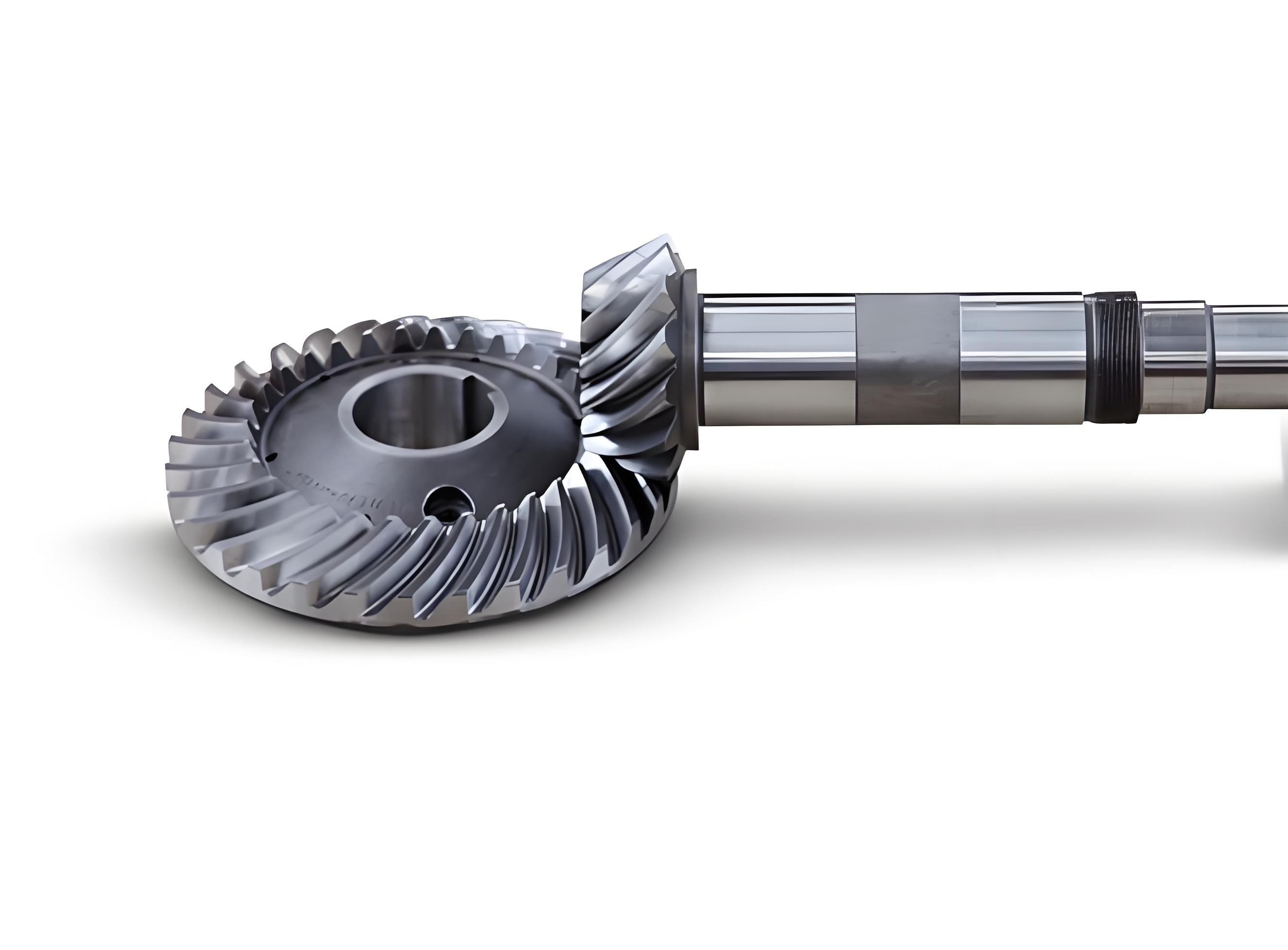
The entire calculation is performed within a fixed coordinate system $S_g$, which was originally established for the gear cutting process. From here, I define a separate coordinate system $S_p$ to describe the pinion generation. The generation process for spiral bevel gears, specifically for the pinion, commonly employs a cutter head tilting method. The geometric meaning of the key machine settings is foundational. Imagine a plane perpendicular to the axis of the generating gear (cradle), passing through the cutter center $O_c$. This is the machine plane. Its intersection with the cradle axis is the machine center $O_m$. The vector from $O_m$ to $O_c$ defines the radial distance $S_r$, and its angle relative to the machine’s horizontal plane is the rotational cradle angle $q$. The spatial orientation of the cutter axis relative to the cradle axis is defined by the tilt angle $i$ and the swivel angle $j$. The pinion’s position is defined by its own axis orientation relative to the cradle: the mounting angle $\gamma_m$, the vertical offset $E_m$, an axial correction value $\Delta X$, and a sliding base setting $X_b$. With the number of teeth on the generating gear being $N_c$, the ratio $R_a = N_p / N_c$ is the machine roll ratio. These nine parameters, along with the spiral motion coefficient, form the complete set for setting up the pinion cutting machine for spiral bevel gears. The interrelationship of these parameters is complex and critical for accurate spiral bevel gear production.
The heart of the precision method lies in matching the curvature of the generated pinion surface to the theoretical surface at the calculated design point. I start by determining the pinion axis direction vector $\vec{k}_p$ within the gear coordinate system $S_g$, using the shaft angle $\Sigma$ and gear mounting angle $\gamma_g$:
$$\vec{k}_p = (-\sin \Sigma, 0, \cos \Sigma – \sin \gamma_g).$$
Using this, along with the unit normal vector $\vec{n}_p$ at the pinion concave side design point and the pinion’s root angle pressure, I can derive the axis direction of the machine cradle $\vec{k}_c$:
$$\vec{k}_c = \frac{\vec{n}_p \times \vec{k}_p}{|\vec{n}_p \times \vec{k}_p|}.$$
A vector $\vec{i}$ perpendicular to the machine plane is then:
$$\vec{i} = \vec{k}_c \times \vec{j},$$
where $\vec{j}$ is a suitably defined horizontal vector. The coordinate system $S_c$ for pinion generation is thus established with origin at $O_g$ and axes defined by $\vec{i}$, $\vec{j}$, and $\vec{k}_c$.
The position vector from the machine center $O_m$ to the pinion design point $O_p$ is $\vec{R}_{mp}$. The relative velocity $\vec{v}^{(cp)}$ between the generating gear (cradle) surface and the pinion at the design point is fundamental for applying the gear meshing theory. It is a function of the angular velocity $\omega_c$ and the relative positions:
$$\vec{v}^{(cp)} = \omega_c \times \vec{R}_{cp} + \vec{V}_{s},$$
where $\vec{V}_{s}$ is the relative sliding velocity component along the cradle axis. The condition for continuous tangency (conjugacy) is the scalar product of the relative velocity and the common surface normal must be zero:
$$\vec{n} \cdot \vec{v}^{(cp)} = 0.$$
From this condition, I can solve for the precise machine roll ratio $R_a$ that ensures contact occurs precisely at my calculated design point for the spiral bevel gear pair. By rotating the pinion through an angle $\varphi_p$, I transform the design point back to its generation position, finding the corresponding conjugate contact point on the imaginary generating gear surface, defined by its position vector $\vec{R}_c$ and normal $\vec{n}_c$.
Next, I analyze the curvature. The relative angular velocity $\vec{\omega}^{(cp)}$, relative velocity $\vec{v}^{(cp)}$, and relative acceleration $\vec{a}^{(cp)}$ are calculated at the design point. In a local coordinate system $(\vec{e}_1, \vec{e}_2, \vec{n})$ attached to the pinion surface at that point, I express these vectors. The generating surface, typically a cone from the cutter, has known principal curvatures. Let $k_c^{(1)}, k_c^{(2)}$ be the normal curvatures of the generating surface along two orthogonal directions $\vec{e}_{c1}, \vec{e}_{c2}$ in its tangent plane, and $\tau_c$ be its geodesic torsion. According to the theory of surface generation, the corresponding normal curvatures $k_p^{(1)}, k_p^{(2)}$ and torsion $\tau_p$ of the generated pinion surface along the transferred directions can be calculated using the following general relation involving the relative motion parameters:
$$k_p^{(i)} = k_c^{(i)} + \frac{(\vec{\omega}^{(cp)} \times \vec{v}^{(cp)}) \cdot \vec{n}}{(\vec{v}^{(cp)} \cdot \vec{e}_i)^2} \quad \text{(for a simplified case)},$$
with a more complex system needed for the general spatial case. The theoretical pinion surface from the design has its own target curvatures, $k_{pt}^{(1)}$ and $k_{pt}^{(2)}$, along the contact path direction $\beta$. For the generated surface of the spiral bevel gear to match the theoretical one, we enforce:
$$k_p^{(1)} \rightarrow k_{pt}^{(1)}, \quad k_p^{(2)} \rightarrow k_{pt}^{(2)}, \quad \tau_p \rightarrow \tau_{pt}.$$
These curvature matching conditions are vital for controlling the contact ellipse size and orientation under load.
Simultaneously, I must determine the cutter parameters for the pinion to match those of the gear. The geometry of the cutter is defined by the blade angles $\alpha_o$ (outer) and $\alpha_i$ (inner), and the point width. For a given mean point radius $R_{c0}$, the relationship between the blade angle, point radius, and the desired gear tooth form is:
$$\alpha_o = \tan^{-1}\left( \frac{R_{co} – R_{ci}}{W} \right) + \alpha_{\text{ref}},$$
where $W$ is a measure related to tooth depth. I define a vector $\vec{R}_{t}$ representing the midpoint of the cutter blade tip. Through a coordinate transformation and re-applying the conjugation condition $\vec{n}_c \cdot \vec{v}^{(cp)} = 0$, I locate the corresponding contact point on the pinion’s new root line. This allows me to recalculate the actual root angle $\theta_{f\_new}$ of the pinion. To maintain the correct mid-point tooth depth, a correction $\delta_\theta$ to the initial root angle is computed, leading to a final, adjusted root angle. This iterative correction ensures the spiral bevel gear set maintains proper clearance and working depth.
Finally, the core adjustment parameters are solved as a system of nonlinear equations. The variables include the basic machine settings: $S_r$, $q$, $i$, $j$, $\Delta X$, $X_b$, and $\gamma_m$. The equations in the system are the curvature matching conditions and the condition that the calculated mean cutter radius equals that of the gear cutter:
$$
\begin{cases}
k_p^{(1)}(S_r, q, i, …) – k_{pt}^{(1)} = 0 \\
k_p^{(2)}(S_r, q, i, …) – k_{pt}^{(2)} = 0 \\
\tau_p(S_r, q, i, …) – \tau_{pt} = 0 \\
R_{c0\_calc}(S_r, q, i, …) – R_{c0\_gear} = 0 \\
\vdots
\end{cases}
$$
Solving this system yields the numerical values for all key pinion machine settings. The sliding base $X_b$ is often initially set to zero and later derived from the axial movement of the cutter center and the spiral motion. The tilt $i$ and swivel $j$ are extracted from the orientation of the calculated cutter axis vector $\vec{k}_{cutter}$ relative to the cradle axis.
| Parameter | Symbol | Description |
|---|---|---|
| Radial Setting | $S_r$ | Distance from machine center to cutter center. |
| Cradle Angle | $q$ | Angular position of the radial arm in the machine plane. |
| Tilt Angle | $i$ | Angle between cutter axis and cradle axis. |
| Swivel Angle | $j$ | Orientation of the tilt plane relative to the radial direction. |
| Machine Root Angle | $\gamma_m$ | Angle between pinion axis and machine plane. |
| Vertical Offset | $E_m$ | Offset of pinion axis from cradle axis. |
| Axial Correction | $\Delta X$ | Adjustment of pinion mounting position along its axis. |
| Sliding Base | $X_b$ | Bed travel setting to control tooth depth. |
| Roll Ratio | $R_a$ | Ratio of pinion rotation to cradle rotation. |
As a result of the pinion root angle correction, some final gear geometry parameters must be updated to maintain the correct assembly and tooth engagement for the spiral bevel gears. The gear’s face angle $\Gamma_f$ changes to maintain the sum of angles:
$$\Gamma_{f\_new} = \Sigma – \theta_{f\_new}.$$
While mid-point tooth thicknesses and depths are preserved by the calculation, the outer end tooth geometry shifts. The new gear outer addendum $h_{ae\_g}$ and whole depth $h_{t\_g}$ are:
$$h_{ae\_g} = h_{a\_mid\_g} + 0.5 F \tan(\delta_{a\_g\_new}),$$
$$h_{t\_g} = h_{ae\_g} + h_{fe\_p},$$
where $F$ is the face width, $\delta_{a\_g\_new}$ is the new gear addendum angle, and $h_{fe\_p}$ is the pinion outer end dedendum. The outer end working depth remains the difference between whole depth and clearance. The outer diameters of both the gear and pinion are recalculated based on their new pitch and root/face cone elements. The distance from the pinion root cone apex to its pitch cone apex $A_{rp}$ is also adjusted:
$$A_{rp} = \frac{R_{mp} – 0.5 F \tan(\theta_{f\_new})}{\cos(\theta_{f\_new})},$$
where $R_{mp}$ is the mean pinion pitch radius. All other fundamental dimensions of the spiral bevel gear set remain unchanged. This comprehensive methodology, from initial coordinate system definition through curvature matching and nonlinear system solving, ensures the precise and efficient manufacture of high-performance spiral bevel gears using a consistent cutter set and predictable, optimal contact characteristics.