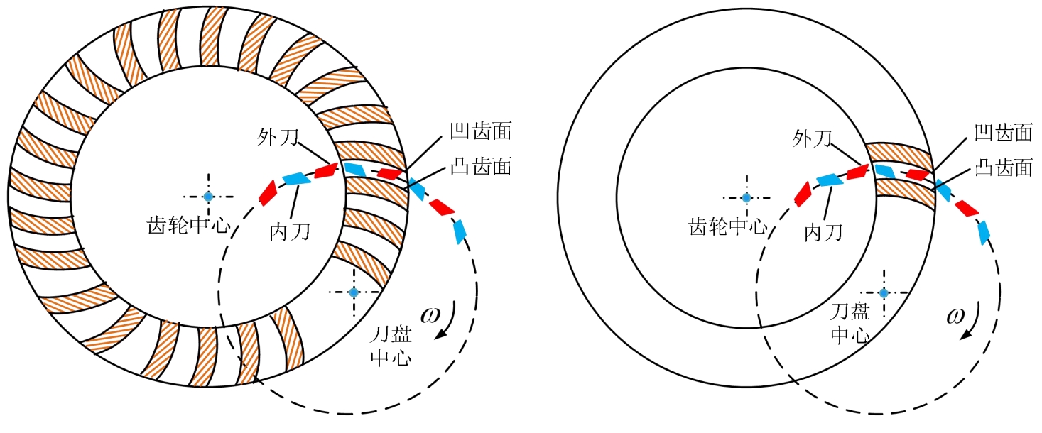
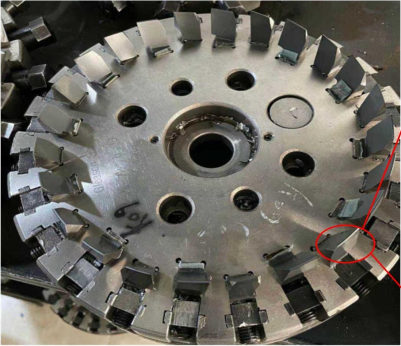
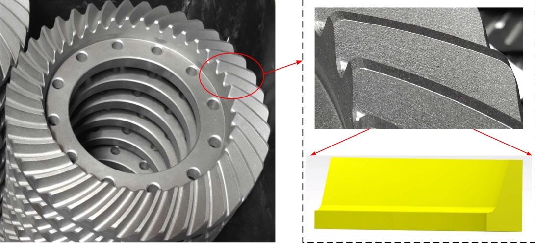
At present, spiral bevel gears are divided into two types of machining methods: generating method and forming method, both of which belong to intermittent cuttingThe processing process. The machining of spiral bevel gears by the generating method involves a cutter head that rotatesCutting is carried out from the tooth tip to the tooth root, and the inner and outer blades of the milling cutter are used to machine the concave tooth surface of the spiral bevel gearThe machining principle of the tooth surface can be seen as a pair of meshing spiral bevel gears as shown in Figure 1.When machining spiral bevel gears by the helical gear machining method, it is necessary to ensure that the workpiece being processed is in a stable state for each tooth groove being machined.The cutter head performs rotational and axial reciprocating movements. When the single groove of the processed tooth blank is completed, the tooth blank willRotate the cutting head to a specific angle to reengage the cutting head with the tooth blank for cutting. The principle of this method is shown in the figure. This method is suitable for high-volume production and high-productivity workpieces.

The process of machining spiral bevel gears by the method of generating curves can be seen as the formation of an imaginary flat-top gear and spiral tooth by cutting edge trajectoriesThe process of meshing of bevel gears is to produce a virtual plane. The meshing principle of the virtual plane generating wheel is shown in FigureAs shown in Figure 1, the main cutting edges of the outer and inner cutting blades of the high-speed rotating milling cutter disk form imaginary planesThe concave and convex tooth surfaces of the shape wheel are respectively represented as a directrix curve and a straight line in the direction of tooth length and profileThe process can be seen as the meshing state of two gears, so the tooth surface of the processed spiral bevel gear is formed by a planeThe profile of the gear wheel is formed, and it exhibits an involute shape in the direction of the tooth profile, which can be utilized in gear meshing theoryProcessing spiral bevel gear.
By analyzing the model and milling principle of the spiral bevel gear, the cutting trajectory and the surface mode of the machined surface areBased on the shape of the workpiece, a more accurate tool wear model and a residual height model of the machined surface are established. The main results are as follows:The following conclusions were drawn:According to the principle of spiral bevel gear milling, the tool and the processing area of the spiral bevel gear are brieflyand obtain the cutting cone model of the concave and convex tooth surfaces of the spiral bevel gear, and derive the cutting surface equation to exploreThe cutting trajectory equation of the tool during cutting.(2) Discuss the motion trajectory of the tool and establish a tool wear model; obtain the tool wear parameters through concave and convex conical surfaces.Obtain the residual height model of the processed surface, and use Matlab software to visualize the tool wear.Analyze the influencing factors of tool wear and the formation mechanism of surface residual height, in order to explore the mechanism of tool wear and surface residual height formation in the follow-up research.The study of the form, mechanism, and surface roughness of spiral bevel gears provides a theoretical basis.

According to the cutting principle of spiral bevel gears, the trajectory of the cutting tool in the cutting process of spiral bevel gears on the tooth blank can beThe trace is an extended epicycloid, and only the model of the workpiece blank needs to be simplified, retaining the tooth blank model with a single tooth groove.

During the cutting process of spiral bevel gears, cutting parameters have a significant impact on the surface quality of spiral bevel gears and the wear of cutting tools.There are different degrees of influence; after determining the material properties and cutting conditions of the workpiece being processed, perform cutting simulation analysis.According to relevant research, the influence of backfeed on tool wear and surface quality is relatively small, so cutting speed is selected as the main cutting parameter.The simulation analysis was conducted using the single-factor control variable method, considering two factors: speed and feed rate.
Establish a three-dimensional model of the cutting tool and workpiece for cutting spiral bevel gearsand carried out simulation analysis on the end milling spiral bevel gear through the DEFROM simulation software to explore the cutting process.The wear of medium cutting tools and the deformation law of the machined workpiece surface mainly lead to the following conclusions:(1) Using DEFORM simulation software to conduct cutting simulation, analyze the distribution of cutting forces during the machining process.The variation law and trend show that the cutting force increases with the increase of feed rate, and the cutting force isThe cutting force will increase rapidly, then gradually increase, and finally tend to a stable state; the cutting speed has a greater impact on the cutting force.Significantly.(2) The study found that a large amount of cutting heat was carried away by the workpiece material, and as the cutting area continued to increase,The cutting temperature on the surface of the processed workpiece first increases and then decreases; the cutting temperature at the tip of the toolHigher, mainly concentrated in the arc part of the cutting edge, and the cutting temperature will increase with the increase of cutting speed.However, with the increase of feed rate, the temperature of the tool surface shows a trend of first increasing and then decreasing.(3) Tool wear is mainly concentrated in the area near the front and rear cutting edges of the main cutting edge, and the front cutting edge willThe existing crescent-shaped depression is worn; the surface deformation of the machined spiral bevel gear will increase with the increase of the feed rate, that is, the surfaceThe surface roughness becomes larger, and the deformation of the workpiece surface becomes more obvious as the depth of the actual processed surface increases.The apparent roughness is positively correlated with the actual machining depth, and the cutting speed has a significant impact on the surface roughness of the machined workpiece.The degree of influence is not significant.
The spiral bevel gear belongs to the intermittent cutting process, and the wear pattern of the tool has been studied.But it is necessary to study the wear mechanism of the tool and analyze whether there is any expansion during the cutting process.dispersed wear, oxidative wear and other phenomena. It can be seen that the tool is affected by different cutting speeds andThe cutting wear patterns are roughly the same under the same feed rate conditions, so this section only discusses cutting speed.The wear mechanism of the tool during cutting can be understood. The tool is cut at a cutting speed of 200r/minSEM micrograph of the outer and inner blades; the wear morphology of the outer blade rake surface, workpieceThere are many bonds, and the accumulation of bonds provides the necessary conditions for the formation of chip build-ups;The wear morphology of the rear flank of the tool shows obvious hard spot scratches, indicating that the rear flank is mainly abrasive wear.To investigate the element diffusion between the tool and the workpiece, elemental energy spectrum analysis was performed on the worn area.The worn area of the tool contains the main elements Cr and Ti of the processed workpiece 20CrMnTi.Mn, indicating that there is a phenomenon of diffusion wear in this area, indicating that the front surface mainly experiences adhesive wear and diffusion wear.The phenomenon of damage and micro-breakage of the cutting edge is mainly caused by abrasive wear on the flank.
With the increase of cutting speed, the roughness of the machined gear surface showsA decreasing trend can be seen, indicating that cutting speed can improve the surface roughness of the machined workpiece; when the cutting speed reachesWhen the cutting speed reaches 300r/min, the roughness of the processed gear surface is slightly higher than that of the spiral gear with a cutting speed of 250r/min.The surface roughness of bevel gears is mainly due to increased wear or breakage of the cutting tool as the cutting speed increases.The cutting environment is deteriorated due to cutting conditions such as wear and tear, so excessive cutting speed can also lead to rough machined surfaces.Degree of variation.
With the increase of feed rate, the surface roughness of the processed spiral bevel gears shows ashows an increasing trend; comparing the influence of cutting speed, it can be seen that the feed rate has aThe influence is greater than the influence of cutting speed on surface roughness, mainly due to the increase in feed rate during the process.It is easy to cause severe tool wear and deteriorate the cutting environment, so the cutting parameters should be adjustedThe reasonable selection of cutting tools can not only reduce tool wear and the surface roughness of the processed workpiece, but also improve production efficiency.Efficiency.
Experiments were conducted on carbide cutting tools for spiral bevel gears under different cutting parameters, and the results were analyzed using super-depth microscopy.The wear forms and wear mechanisms of the tool were analyzed using mirrors, scanning electron microscopes, and energy spectrometers, and P40The rolling inspection machine measures the residual height of the processed workpiece surface to calculate the surface roughness. Based on the aboveThe study mainly reached the following conclusions:(1) Under the same cutting parameters, the wear amount and wear pattern of the outer and inner blades are different.The wear of the tool is characterized by a slightly higher wear amount on the outer blade than on the inner blade, and the wear location of the tool is mainlyConcentrated on the main cutting edge and the front and rear cutting surfaces near the main cutting edge. Therefore, it is recommended that the tool bar be used on the tool diskThe distribution of “inner blade-middle blade-outer blade” can improve the service life of the tool and increase the processing efficiency.The rate.(2) Under different cutting speeds, the failure mode of the tool also changes accordingly;When n<200r/min, the wear modes of the outer and inner blades are mainly adhesive wear, abrasive wear, and diffusion wearWhen the cutting speed n=200~300r/min, the wear patterns of the outer and inner blades are mainly crescent wear, adhesive wear, and diffusion wear, and there is oxidative wear on the inner blade. When the cutting speedWhen n>300r/min, chipping is the main failure mode.(3) It is found that increasing the cutting speed within a certain range can reduce the roughness of the machined workpiece surface.Roughness, ensuring a good cutting environment; as the feed rate increases, the surface roughness of the processed workpieceThe increasing trend is mainly due to the increase in cutting force of the tool with the increase in feed rate, which leads to theThe tool may crack or break; from the experimental results, it can be seen that the feed rate has a significant impact on the surface roughness of the processed workpiece.The influence of roughness is more significant.
