
In my extensive experience analyzing component failures within power transmission systems, the integrity of the gear shaft is paramount. This critical component is responsible for transmitting torque and rotation, often under significant cyclic loads. A failure in the gear shaft does not merely halt a single machine; it can precipitate catastrophic breakdowns across entire operational lines. Therefore, when a batch of carburized gear pump driving gear shafts exhibited surface cracking post-heat treatment, a detailed and systematic forensic investigation was immediately warranted. The objective was not only to pinpoint the immediate cause but to unravel the underlying metallurgical phenomena that created a set of conditions ripe for failure, ensuring such issues are designed out of future manufacturing processes.
The presented case involved 49 units of a driving gear shaft, fabricated from low-alloy carburizing steel 16Cr2MnTiA. The specified heat treatment sequence involved carburizing at 925±10°C for 3.5 hours, followed by furnace cooling (or air cooling, as per some records) to room temperature. This was to be followed by a subsequent reheat, quenching, and tempering operation. However, after the initial carburizing and cooling cycle, 8 out of the 49 gear shafts were found to possess prominent longitudinal cracks. Visually, these cracks were located on the elongated end of the gear shaft and propagated approximately 40 mm along its length. A transverse cross-section through the cracked region revealed a more sinister detail: the crack was not merely superficial. It originated beneath the surface, within the carburized case, and propagated both circumferentially through the case and longitudinally to break the surface, forming a characteristic “T-shaped” or inverted-L morphology. This was an immediate red flag, indicating that the failure mechanism was driven by internal stresses generated during phase transformations, not by surface flaws or machining defects.
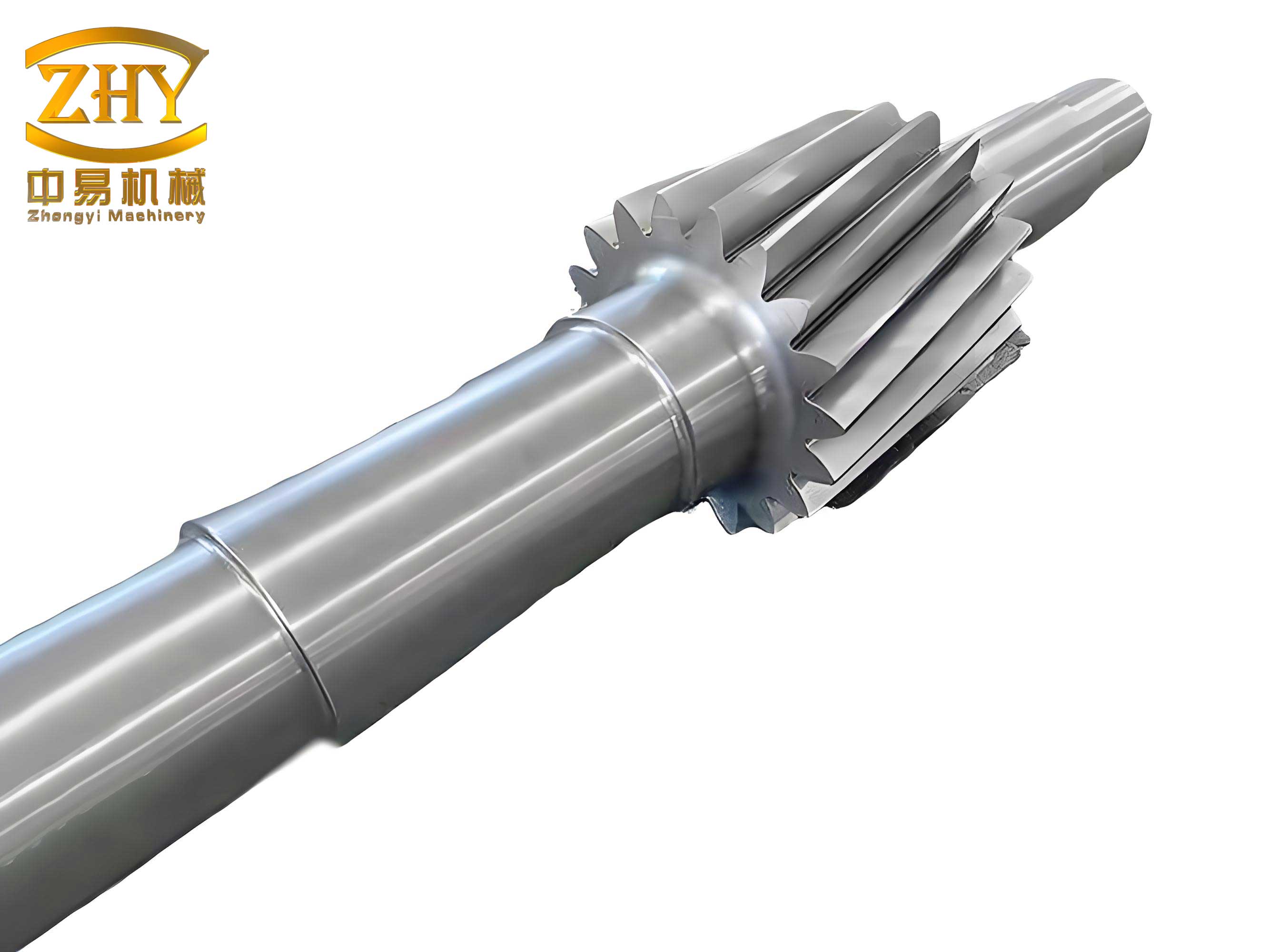
The first step in my analysis was to verify the material conformance. Chemical analysis of the failed gear shaft was conducted via optical emission spectroscopy. The results, compared against the relevant material specification, are presented in the table below.
| Element | C | Cr | Mn | Ti | Si | P | S |
|---|---|---|---|---|---|---|---|
| Measured Value | 0.16 | 1.67 | 1.05 | 0.031 | 0.334 | 0.013 | 0.015 |
| Specification (Typical) | 0.13-0.18 | 1.50-1.80 | 1.00-1.30 | 0.06-0.12 | 0.17-0.37 | ≤0.025 | ≤0.025 |
While most elements were within acceptable ranges, the Titanium (Ti) content was notably low. Ti is a potent grain-refining element added to prevent austenite grain growth during high-temperature carburizing. A deficiency could potentially lead to coarse grains, impacting toughness. However, subsequent microstructural examination did not reveal excessive grain growth. The primary finding lay elsewhere. The effective case depth was measured to be 0.75 mm, which was within the specified range of 0.5 to 0.8 mm. Upon etching and observing the microstructure under a scanning electron microscope, the anomaly became clear. The expected microstructure for a low-alloy steel like 16Cr2MnTiA after carburizing and air cooling should transition smoothly from surface to core: a thin layer of carbides and pearlite, followed by a broader zone of pearlite, then a transition zone, and finally the ferrite-pearlite core structure.
Instead, the failed gear shaft exhibited a starkly different sequence. Directly beneath the surface carbides and pearlite, at a depth of approximately 0.5 mm, there existed a continuous, well-defined layer of untempered martensite. Beneath this martensitic band, the microstructure reverted to pearlite and then the core ferrite-pearlite mix. Critically, the circumferential branch of the “T” crack was found to propagate precisely within or along the boundaries of this brittle martensite layer. The longitudinal crack then extended from this point to the surface. The formation of this isolated martensite band in an otherwise predominantly pearlitic matrix was the key to understanding the failure.
To understand this, we must delve into the fundamentals of hardenability and continuous cooling transformation. The hardenability of a steel, its ability to form martensite, is not a fixed value but varies with chemical composition, particularly carbon content. The critical cooling rate ($V_{crit}$), the minimum rate required to avoid diffusion-controlled transformations (like pearlite) and form martensite, follows a non-linear relationship with carbon content. For most low-alloy steels, $V_{crit}$ is highest for very low-carbon ferritic compositions, decreases to a minimum near the eutectoid composition (~0.8 wt% C), and then increases again for hypereutectoid steels. This relationship can be approximated for a given alloy system by an equation considering the carbon (C) and alloying element effects:
$$ \log V_{crit} = A – B \cdot C_{eq} $$
where $C_{eq}$ is a carbon equivalent accounting for alloying elements like Mn and Cr, and A & B are empirical constants.
In a carburized gear shaft, the carbon profile is not uniform. It is high at the surface (often >0.8%) and decreases gradually to the core level (~0.16%). Therefore, at different depths, the local chemical composition, and hence the local $V_{crit}$, is different. We can model the carbon profile after carburizing using Fick’s second law for a semi-infinite solid:
$$ C(x,t) = C_s – (C_s – C_0) \cdot \text{erf}\left( \frac{x}{2\sqrt{Dt}} \right) $$
where $C(x,t)$ is the carbon concentration at depth $x$ after time $t$, $C_s$ is the surface carbon concentration, $C_0$ is the initial core carbon, $D$ is the diffusion coefficient, and erf is the error function.
| Depth from Surface | Approx. Carbon % | Local $V_{crit}$ | Microstructure after Very Slow Cool | Microstructure after Very Fast Quench | Microstructure after Intermediate Cool (Failure Scenario) |
|---|---|---|---|---|---|
| Surface (0-0.2 mm) | >1.0% | High | Pearlite + Cementite Network | Martensite + Retained Austenite + Carbides | Pearlite + Carbides |
| Sub-surface (0.4-0.6 mm) | ~0.7-0.9% | Minimum | Pearlite | Martensite | Martensite |
| Transition Zone (0.7-1.0 mm) | ~0.4-0.6% | High | Pearlite + Ferrite | Martensite/Bainite | Pearlite + Ferrite |
| Core | ~0.16% | Very High | Ferrite + Pearlite | Ferrite + Martensite/Bainite | Ferrite + Pearlite |
The failure mechanism becomes clear when analyzing Table 2. During the air-cooling process after carburizing, the cooling rate was not uniform but fell within a specific window. It was slower than the $V_{crit}$ for the high-carbon surface layer and the lower-carbon transition zone/core, allowing them to transform to softer pearlite/ferrite. However, it was coincidentally faster than the absolute minimum $V_{crit}$ present in the sub-surface zone with near-eutectoid carbon content. This created an isolated, continuous band of hard, brittle, untempered martensite embedded within a much softer and more ductile matrix of pearlite.
The formation of martensite is accompanied by a significant volumetric expansion due to its body-centered tetragonal (BCT) crystal structure, which has a larger specific volume than the parent austenite. This transformation-induced strain generates substantial internal stresses. In a typical through-hardened component, these “transformation stresses” or “phase transformation stresses” interact with “thermal stresses” (from uneven cooling). The thermal stresses during cooling usually place the surface in compression, which can inhibit cracking. However, in this scenario with the gear shaft, the situation was profoundly different and dangerous.
Since the surface and core transformed to pearlite/ferrite first (at higher temperatures), they contracted thermally and began to behave elastically. Subsequently, the isolated sub-surface band transformed to martensite upon cooling to its lower martensite start ($M_s$) temperature. The expansion of this band was constrained by the already-solidified and stronger outer surface layer and the inner core. This created a complex triaxial stress state within the martensite band. The primary stresses were:
1. Hoop (Circumferential) Tensile Stress ($\sigma_\theta$): The martensite layer’s expansion against the constraint of the cylindrical geometry generated high tensile stresses tangential to the gear shaft‘s circumference.
2. Radial Tensile Stress ($\sigma_r$): A tensile stress acting outward, trying to push against the surface layer.
3. Axial Stress ($\sigma_z$): The stress along the length of the gear shaft.
The stress state can be conceptualized using a thick-walled cylinder model, where the martensite layer is the inner layer trying to expand. The hoop stress is often the most critical for crack initiation. The maximum hoop stress within the transforming layer can be estimated by:
$$ \sigma_{\theta, max} \approx \frac{E \cdot \beta \cdot \Delta V}{3(1-\nu)} $$
where $E$ is Young’s modulus, $\beta$ is a constraint factor, $\Delta V$ is the volumetric strain due to the austenite-to-martensite transformation (~0.04), and $\nu$ is Poisson’s ratio. For untempered martensite, which has high strength but very low fracture toughness and ductility, this internally generated tensile stress easily exceeded its fracture strength. Consequently, a crack initiated in the most highly stressed region—within the martensite band—and propagated circumferentially, following the path of least resistance through the brittle phase. The longitudinal crack to the surface was a secondary event, likely driven by a combination of the axial stress component and stress concentration at the tip of the circumferential crack.
The low Ti content, while not the root cause of cracking, is a relevant finding. Ti, through the formation of stable TiN and TiC particles, pins austenite grain boundaries. Its deficiency can lead to marginally larger prior austenite grains during carburizing. This slightly reduces toughness and can make the martensite even more prone to cleavage fracture, potentially lowering the critical stress intensity factor ($K_{IC}$) required for crack propagation. Thus, while it didn’t cause the unique “T” crack, it may have contributed to the severity and likelihood of propagation once the crack initiated.
The primary corrective and preventive actions stem directly from the root cause analysis. The goal is to avoid creating the isolated martensite band by shifting the entire cooling profile out of the dangerous intermediate window. Two robust strategies exist:
Strategy 1: Accelerated Cooling (e.g., Forced Air Blast or Oil Quench).
This ensures the cooling rate $V_{cool}$ exceeds the $V_{crit}$ for the entire carburized case depth, expressed as:
$$ V_{cool} > \max(V_{crit}(C(x))) \quad \text{for } 0 \le x \le \text{Case Depth} $$
The result is a fully martensitic case, which generates more uniform transformation stresses. While these parts are highly stressed and must be tempered immediately, the stress state is less triaxial and severe than the isolated band scenario, making cracking less probable. This is often the preferred method for high-reliability components, as it also minimizes the formation of intergranular oxidation.
Strategy 2: Decelerated Cooling (Furnace Cooling or Pack Cooling in Insulating Media).
This ensures the cooling rate is slower than the minimum $V_{crit}$ throughout the case:
$$ V_{cool} < \min(V_{crit}(C(x))) \quad \text{for } 0 \le x \le \text{Case Depth} $$
This guarantees a fully pearlitic microstructure, which is soft and machinable, and generates minimal transformation stress. This is the safest approach to prevent cooling cracks and is highly recommended for components that will undergo subsequent machining before reheat and quench. The trade-off is longer process time and potential for more surface oxidation.
| Strategy | Cooling Method | Expected Case Microstructure | Internal Stress State | Risk of “T” Cracking | Key Advantage | Key Disadvantage |
|---|---|---|---|---|---|---|
| Original (Failed) | Still Air Cool | Mixed: Pearlite + Isolated Martensite Band | Severe, Triaxial Tension in Martensite Band | Very High | Simple, Low Cost | Unpredictable, High Scrap Rate |
| Strategy 1 | Forced Air Blast / Oil Quench | Full Martensite (to be tempered) | High but More Uniform | Low (with immediate temper) | Fine Microstructure, Good for Performance | Higher Distortion, Requires Immediate Tempering |
| Strategy 2 | Furnace Cool / Pack Cool | Full Pearlite | Very Low | Negligible | Very Safe, Minimizes Cracking & Distortion | Longer Cycle Time, Softer for Machining |
Furthermore, process control and monitoring are critical. Implementing precise monitoring of cooling rates using thermocouples attached to dummy gear shafts can map the actual cooling profile against the calculated CCT (Continuous Cooling Transformation) diagram for the specific steel grade and carburizing profile. Finite Element Analysis (FEA) can be employed to model temperature fields and stress evolution during cooling for different gear shaft geometries, providing a predictive tool to identify potential crack risks before physical manufacturing.
In conclusion, the longitudinal “T” cracking in the driving gear shaft was a direct consequence of a non-uniform cooling rate following carburizing, which selectively transformed a sub-surface layer with near-eutectoid carbon content into martensite while the surrounding material transformed to softer phases. The volumetric expansion of this constrained, isolated martensite band generated intolerable triaxial tensile stresses, leading to brittle fracture within the band itself. This failure highlights a critical window in process design for carburized components. It is not merely about “slow” or “fast” cooling, but about comprehensively avoiding the intermediate cooling rate zone that intersects the nose of the CCT curve only at a specific carbon concentration range within the case. The corrective path is clear: actively control the post-carburizing cooling to be either uniformly fast enough to through-harden the case or uniformly slow enough to fully soften it, thereby eliminating the conditions for this deleterious microstructural banding and ensuring the reliable performance of the gear shaft. This investigation underscores that the durability of a power transmission system is fundamentally linked to a deep, quantitative understanding of the metallurgical transformations imposed upon its core components, such as the humble yet indispensable gear shaft.