

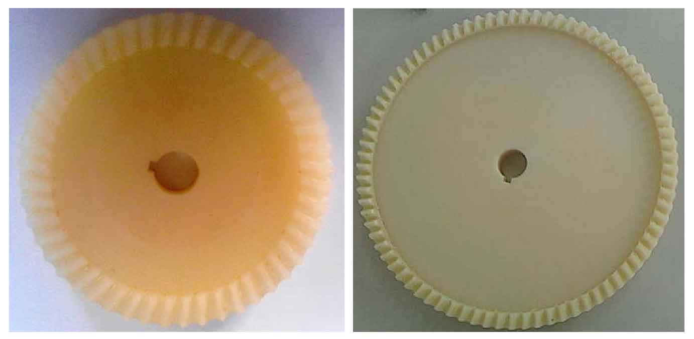
When hobbing helical gear, first check the correctness of fixture installation, the accuracy of tool setting and the adjustment of relevant parameters, and then hobbing. Fig. 1 is a hobbing view of a helical gear. Fig. 2 shows two helical gears with different parameters after successful gear hobbing, of which the main parameters of face gear in Fig. 2 (a) are Mn = 5.2mm; β °= 10 ; Rw=75 mm; Rn=60 mm; Z2=48 ; B=15mm。 Main parameters in Figure 2 (b): Mn = 5.2 mm; β °= 10 ; Rw=115 mm; Rn=105 mm; Z2= 80; B=10mm。
The following problems were encountered and solved during processing:
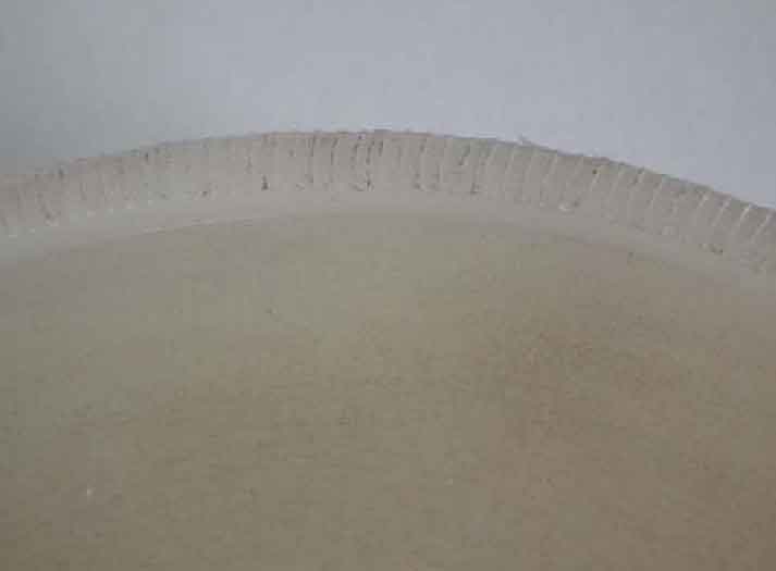
((1) When processing helical gear on gear hobbing machine, because a pair of bevel gear pairs are added in the processing process, and their transmission ratio is 1:1, the rotation direction of the processed workpiece is changed. If the split change gear and differential change gear are matched according to normal conditions, all the teeth on the gear blank will be cut off. As shown in Figure 3. In order to solve the problem of cutting all the teeth in the above processing, the correct processing scheme is obtained through several processing tests. The left-hand hob is used for hobbing the helical gear (right-hand). According to the actual processing situation, the matching of the split change gear should be matched according to the matching of the split change gear when the right-hand hob is used for hobbing (i.e. remove the z36 teeth of the reversing gear), in order to change the rotation direction of the gear to be processed. The differential change gears shall be matched according to the normal processing with left-hand knife. With the combination of the above split change gears and differential change gears, helical gears can be processed on an ordinary hobbing machine.
(2) When the back draft is too large, the cutting force increases, which affects the stability of the combined fixture. Therefore, the back draft cannot be equal to the tooth height, which can be processed in four times.
(3) Because the hob must modify the tooth profile of the helical gear during machining the helical gear, raise the hob about 20cm away from the workpiece before machining. Stop the machine from the beginning of machining until the hob no longer cuts the workpiece.