
The schematic diagram of the seedling taking mechanism of non-circular gear planetary gear train is shown in the figure. The mechanism is symmetrically arranged with two arms. The transmission process is analyzed by the upper right half of the mechanism: the planet carrier 1 is hinged with the sun gear 2 fixed on the frame, the intermediate wheel 3 is hinged with the star carrier 1 after the intermediate wheel 4 is fixedly connected, and the seedling taking arm 6 is hinged with the star carrier 1 after the planetary wheel 5 is fixedly connected, The intermediate gear 4 is connected with the gear pair of sun gear 2, and the intermediate gear 3 is connected with the gear pair of planetary gear 5. Driven by the central shaft o, the planet carrier rotates counterclockwise at a uniform angular speed.
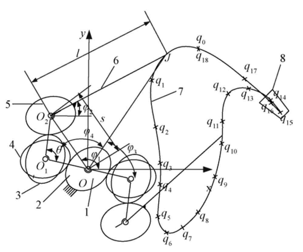
Note: qi(i=0,1,…,18) is data points; θ is angle of planet carrier, (°). s is length of planet carrier OO2, mm. l is length of picking-up seedling arm O2J, mm. J is endpoint of picking-up seedling arm. φ1 is angle between OO2 and x axis, (°). φ2 is angle between picking-up seedling arm and x axis, (°). φ3 is angle between OJ and x axis, (°). φ4 is angle of triangle O2OJ, (°). Same as below.
Step 1: design the expected trajectory of the mechanism. The rectangular coordinate system is established with the central axis O shown in the figure. The basis of reverse engineering design is the pre-designed target track. According to the 19 points on the given track counterclockwise as shown in the figure (the first and last Qi (I = 0,1,…, 18) data points coincide), the cubic non-uniform B-spline fitting method is selected, Taking Qi (I = 0,1,…, 18) as the data point of the corresponding control point of the reverse trajectory curve, 21 control vertices di (I = 0,1,…, 20) can be obtained. Any point P (U) on the seedling trajectory curve can be calculated by using the control vertex Di and according to the debour recursive formula.
Step 2: reverse the total transmission ratio of non-circular gear planetary gear train mechanism. Calculate the length of seedling arm and planet carrier according to the coordinates of track points in the whole movement process obtained in the first step. According to the maximum distance and minimum distance between the motion track point and the coordinate center:

Where: s is the length of oo2, mm; L is the length of O2 J, mm; XP and YP are the abscissa and ordinate of track point J, mm.
According to the analysis of the motion law of the mechanism, the included angle between the clockwise rotation of oo2 and the positive direction of x-axis is obtained during the movement of the end point J of the seedling arm from the farthest point of the track to the nearest point φ 1 calculated by formula.

Where: φ 1 is the included angle between the clockwise rotation of oo2 and the positive direction of X axis, (°); ϕ 3 is the included angle between the clockwise rotation of OJ and the positive direction of X axis, (°); ϕ 4 is the internal angle of triangle o2oj, (°).
The included angle between the clockwise rotation of oo2 and the positive direction of the x-axis is calculated by the formula when the end point of the seedling taking arm moves from the nearest point of the track to the farthest point:

The position can be judged by the coordinate system in the trajectory and graph φ 3 ∈ [- π / 2, π / 2], obtained directly by arctangent φ 3. Such as formula.

Then it is obtained directly from the inverse sine φ 4。

Where: φ 4 is the internal angle of triangle o2oj, φ 4∈[0,π]。
The rotation angle of planet carrier corresponding to each coordinate point can be obtained by the formula φ 1。
On the basis of the calculation, the angle between the seedling arm and the x-axis is obtained by using the arctangent function φ 2。


Where: 2 o x and 2 o y are the abscissa and ordinate of the end point of the seedling arm, mm, φ 1∈[−π/2, π/2], φ 2∈[−π/2, π/2]。
Through the above solution, we can obtain the corresponding value of each point of the trajectory φ 1 value and φ 2 value to determine φ 1 and φ 2, the total transmission ratio I25 of the two-stage gears is:

Where: I25 is the total transmission ratio of two-stage gears.
Step 3: distribution of total transmission ratio of non-circular gear planetary gear train mechanism and solution of gear pitch curve. In order to make the two-stage non-circular gear have similar kinematic and dynamic performance, the distribution goal of the total transmission ratio is set as follows: the transmission ratio of the two-stage non-circular gear should have similar amplitude period ratio. Therefore, the calculation formula of transmission ratio is set as:

Where: I1 is the transmission ratio between the first stage non-circular gears; I2 is the transmission ratio between the second stage non-circular gears; BS is the adjustment coefficient of peak valley value of transmission ratio. The calculation of gear pitch curve and tooth profile data from transmission ratio is described in many documents and omitted here.