
I approach the roll design for hot-rolled gear hob blanks as a complete manufacturing system rather than as an isolated tooling calculation. The starting point is the replacement of conventional machined or forged gear blanks with a three-roll cross-rolled preform. In my method, the roll profile, the blank volume, the thermal allowance, the guide-wheel geometry, and the rolling schedule are calculated together so that the resulting gear hob blank has a stable tooth pitch, a sound metal flow line, and a predictable finishing allowance. The expression forged gear blanks appears throughout my design logic because the comparison basis is always the conventional forged gear blanks route: I want the hot-rolled preform to be at least as reliable as forged gear blanks while removing most of the rough machining and hammer operations. The main technical advantage I obtain is a near-net or net-shape gear hob blank with a continuous grain flow along the tooth profile, lower energy consumption, lower noise, and a much shorter process chain than that used for forged gear blanks.
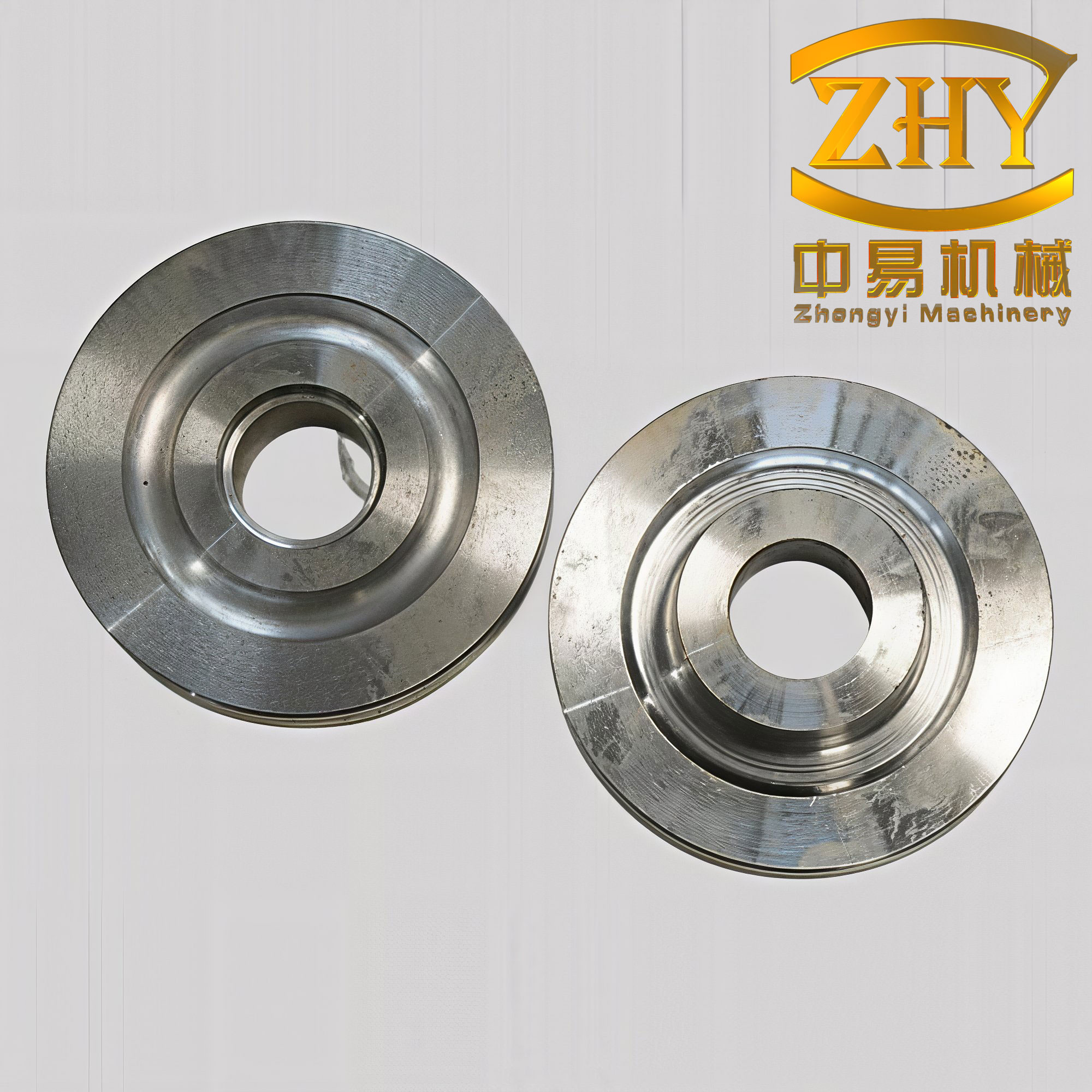
In my experience, the economic case for replacing forged gear blanks with hot-rolled gear hob blanks is strongest when the blank is a long, helical, tooth-like body that can be formed by a three-roll cross-rolling machine. The rolls are single-start left-hand rolls whose helix angle is smaller than the workpiece helix angle, and the roll axis is installed at an angle equal to the difference between the workpiece helix angle and the roll helix angle. This arrangement gives a simple roll structure, stable pitch control, easy storage, and convenient operation. The penalty is that the roll pitch is special and must be cut and ground on a machine capable of generating that special pitch. I accept this penalty because the resulting process is much more stable than the alternative axial-stagger arrangements, and because the dimensional control of the rolled gear hob blank is better when the roll set is designed around a circumferential stagger.
Process comparison. I use the following comparison when I justify the transition from forged gear blanks to hot-rolled gear hob blanks. The table is not a financial audit; it is a design checklist that tells me which variables must be controlled in the roll and blank calculation.
| Item | Conventional forged gear blanks | Hot-rolled gear hob blanks in my design |
|---|---|---|
| Primary forming route | Billet heating, forging, normalization, rough turning, gear milling or hobbing | Billet heating, three-roll cross rolling, controlled cooling, finish machining allowance |
| Material utilization | Lower because of flash, scale, and large machining allowance | Higher because the helical tooth body is formed close to final size |
| Metal flow line | Often cut by machining after forging; local discontinuities may remain | Continuous along the tooth flank and root; the flow line is not cut by rough machining |
| Typical defects | Center cracks, laps, hammer-induced variation, trimming cracks | Pitch drift, fish-mouth at the tail, overfill, and guide-wheel marks if the rolls are poorly designed |
| Automation | Difficult because of impact loading and manual handling | Good; the rolling machine can be arranged for semi-automatic production |
| Working environment | High impact, high noise, intensive manual work | Lower impact, lower vibration, lower noise, reduced labor intensity |
I do not treat forged gear blanks as a inferior product. Rather, I treat forged gear blanks as the reference route that defines the required mechanical properties and the acceptable defect level. The hot-rolled route must meet or exceed that reference. In the rolled condition, the grain flow follows the tooth form and joins the root and flank into one continuous body. After heat treatment, this flow pattern supports a fine-grain structure and a favorable carbide distribution. In the gear hob application, the resulting hardness, red hardness, and toughness are more uniform than in a machined forged gear blank. That is why I pay close attention to the roll groove design and to the blank volume calculation; both determine whether the advantage over forged gear blanks is actually realized.
Machine and product scope. I define the machine scope before I calculate the roll. The three rolls are spaced at 120 degrees around the workpiece axis. Each roll has the same pitch, the same helix angle, and the same axial position. The rolls form a helical tooth profile by circumferential stagger. The gear hob blank is heated to the rolling temperature, fed into the roll gap, and rotated by the rolls. The radial compression is applied gradually in the conical forming section, and the final pitch and flank finish are established in the cylindrical finishing section. The guide wheels behind the rolls control the outside diameter and suppress the rocking motion that occurs when the center of gravity of the blank leaves the finishing tooth. This detail is important because a free tail can produce a pitch error of the order of one millimeter if the blank is allowed to oscillate.
I use the following representative product and blank dimensions to set the calculation sequence. These values are the kind of input data I require before any roll drawing is released.
| Parameter | Symbol | Representative value |
|---|---|---|
| Gear hob blank outside diameter | $$D_{bo}$$ | $$64\ \mathrm{mm}$$ |
| Gear hob blank pitch diameter | $$D_{bm}$$ | $$56\ \mathrm{mm}$$ |
| Gear hob blank root diameter | $$D_{br}$$ | $$44\ \mathrm{mm}$$ |
| Workpiece tooth height | $$h_w$$ | $$10\ \mathrm{mm}$$ |
| Workpiece axial pitch | $$p_a$$ | $$12.56\ \mathrm{mm}$$ |
| Workpiece helix angle | $$\lambda_w$$ | $$4^\circ 44’$$ |
| Workpiece normal pressure angle | $$\alpha_n$$ | $$20^\circ$$ |
| Tooth top width | $$b_w$$ | $$4\ \mathrm{mm}$$ |
| Roll material | — | Hot-work tool steel, hardened and tempered |
| Roll life target | $$N_r$$ | Several thousand pieces per regrind cycle |
Roll type selection. I select a single-start left-hand roll. The roll helix angle is smaller than the workpiece helix angle. The installation angle is the difference between the two helix angles. The sign convention must be fixed in the drawing because a left-hand roll and a left-hand workpiece can otherwise be assembled in the wrong relative orientation. I use the following relation as the installation angle:
$$ \theta = \left| \lambda_w – \lambda_r \right| $$
where $$\theta$$ is the roll installation angle, $$\lambda_w$$ is the workpiece helix angle, and $$\lambda_r$$ is the roll helix angle. If the roll and workpiece have the same hand, the angle is the difference. If they have opposite hands, the angle is the sum. In my design I keep the single-start arrangement because it gives a simple lead, a stable axial pitch, and a robust roll body. The main drawback is that the roll pitch is not a standard value; it must be generated on a machine with a special lead. I include that requirement in the manufacturing specification rather than trying to force the roll to a standard pitch.
| Roll feature | Design choice | Reason |
|---|---|---|
| Number of starts | Single start | Simple structure, stable pitch, easy use and storage |
| Hand | Left hand | Matches the selected rolling kinematics and workpiece hand |
| Helix angle relation | $$\lambda_r < \lambda_w$$ | Keeps the installation angle small and the axial force manageable |
| Stagger method | Circumferential | Equal radial reduction at each roll and smoother rolling |
| Forming section | Conical with mixed press-in | Good bite, gradual compression, and balanced tooth strength |
| Finishing section | Cylindrical | Final pitch correction and flank smoothing |
Roll outside and root diameters. I determine the roll root diameter first and then derive the outside diameter. This order is deliberate. If the outside diameter is used as the datum, the number of guide-wheel sizes increases because the guide wheels must follow the outside diameter. If the root diameter is used as the datum, the guide wheels can be arranged around the root reference and the outside diameter can be controlled by a smaller set of guide wheels. The following relations are the ones I use:
$$ D_{ro} = D_r + 2\left(h_r + \delta\right) $$
$$ D_{rm} = D_r + h_r + \delta $$
$$ D_{rw} = D_{bo} + 2\delta_g $$
In these equations, $$D_{ro}$$ is the roll outside diameter, $$D_r$$ is the roll root diameter, $$h_r$$ is the roll tooth height, $$\delta$$ is the clearance between the blank tooth top and the roll tooth bottom, $$D_{rm}$$ is the nominal roll pitch diameter, $$D_{rw}$$ is the guide-wheel outside diameter, $$D_{bo}$$ is the blank outside diameter, and $$\delta_g$$ is the guide-wheel clearance. I normally take $$\delta$$ in the range of 0.2 to 0.4 mm for a small gear hob blank and slightly larger for a heavy blank. I take $$\delta_g$$ according to the thermal shrinkage and the spring-back of the rolling machine. The guide wheel is not a passive support; it is a diameter-control element, so its diameter must be calculated with the same care as the roll diameter.
The ratio of roll diameter to blank diameter is another decision I make early. If the roll diameter is too small, the contact conformity is good and the rolling force is lower, but the roll strength and stiffness are poor. If the roll diameter is too large, the stiffness is good, but the machine window and the guide-wheel arrangement become restrictive. In my practice, the ratio of roll diameter to blank diameter is kept in a moderate range, typically about 2.5 to 3.5 for gear hob blanks. I verify the ratio against the roll neck strength, the bearing capacity, and the guide-wheel space before I freeze the layout.
| Diameter item | Basis | Typical rule I apply |
|---|---|---|
| Roll root diameter | Roll strength and bearing seat | Chosen from the roll body stiffness and the finishing allowance |
| Roll outside diameter | Root diameter plus tooth height and clearance | $$D_{ro}=D_r+2(h_r+\delta)$$ |
| Roll pitch diameter | Nominal rolling diameter | $$D_{rm}=D_r+h_r+\delta$$ |
| Guide-wheel outside diameter | Blank outside diameter plus clearance | $$D_{rw}=D_{bo}+2\delta_g$$ |
| Roll-to-blank ratio | Stiffness and contact conformity | Approximately 2.5 to 3.5 |
Roll length calculation. I divide the roll length into a conical forming section and a cylindrical finishing section. The forming section does most of the radial compression. The finishing section establishes the final pitch and flank quality. If the forming section is too short, the bite is unstable and the tooth is overfilled. If the finishing section is too short, the pitch does not settle. If the finishing section is too long, the rolling force increases and the finished tooth flank can interfere with the already formed flank.
The conical forming length is calculated from the total radial reduction, the cone angle, and a clearance factor:
$$ L_c = \frac{\Delta}{2\tan\phi} + c $$
where $$L_c$$ is the conical forming length, $$\Delta$$ is the total radial compression, $$\phi$$ is the cone angle of the forming section, and $$c$$ is a clearance constant that accounts for the machine and roll clearances. I use a small cone angle, typically in the range of 2 to 4 degrees for gear hob blanks, because a small angle gives a gradual bite and reduces the risk of fish-mouth formation. The total radial compression is related to the blank and finished diameters by:
$$ \Delta = \frac{D_{blank} – D_{bf}}{2} $$
where $$D_{blank}$$ is the calculated blank diameter and $$D_{bf}$$ is the finished blank diameter after rolling. The finishing length is chosen so that the blank completes a sufficient number of revolutions in the finishing section. I express that condition as:
$$ L_f = n_f \pi D_{rm} \tan\lambda_r $$
where $$L_f$$ is the finishing length, $$n_f$$ is the number of finishing revolutions, and the other symbols have the meanings defined above. I require at least three to five finishing revolutions for a gear hob blank. For a larger blank, I increase the number of finishing revolutions because the thermal gradient and the elastic recovery are larger. The total roll length is then:
$$ L = L_c + L_f + 2e $$
where $$e$$ is the end allowance for the shaft shoulder and the run-out zone. I do not let the end allowance become an arbitrary value. I calculate it from the roll neck, the bearing seat, and the minimum thread run-out required by the grinding wheel.
| Length component | Symbol | Design rule I use |
|---|---|---|
| Conical forming length | $$L_c$$ | $$L_c=\Delta/(2\tan\phi)+c$$ |
| Total radial compression | $$\Delta$$ | $$\Delta=(D_{blank}-D_{bf})/2$$ |
| Finishing length | $$L_f$$ | $$L_f=n_f\pi D_{rm}\tan\lambda_r$$ |
| Finishing revolutions | $$n_f$$ | At least 3 to 5 |
| End allowance | $$e$$ | Set by roll neck, bearing, and grinding run-out |
| Total roll length | $$L$$ | $$L=L_c+L_f+2e$$ |
Groove design in the forming section. I use a mixed press-in groove in the conical forming section. A fully closed press-in groove gives good tooth strength, but it can make the bite too abrupt. A fully layer-by-layer press-in groove gives a gentle bite, but the tooth tip can become thin and weak. The mixed press-in design uses closed press-in teeth near the entry side and layer-by-layer press-in teeth near the finishing side. In my roll layout, the first group of forming teeth is closed, and the last group before the finishing tooth is layered. The transition is arranged so that the tooth strength and the bite condition are balanced.
| Press-in mode | Bite behavior | Tooth strength | Where I use it |
|---|---|---|---|
| Closed press-in | Strong bite, rapid radial compression | High because the tooth is supported on both sides | Entry zone of the conical forming section |
| Layer-by-layer press-in | Gentle bite, gradual compression | Lower at the tooth tip if used alone | Exit zone of the conical forming section |
| Mixed press-in | Combines stable bite with gradual compression | Balanced along the forming section | Full forming section for gear hob blanks |
For the correction teeth in the forming section, I use the fixed chordal tooth thickness of the finishing tooth as the reference. If the reference chordal thickness is $$s_0$$, the correction amount on each flank is $$\Delta_s$$. The corrected chordal thickness becomes:
$$ s_c = s_0 \pm \Delta_s $$
The plus sign applies to the front flank correction and the minus sign applies to the rear flank correction, or the reverse, depending on the direction in which I want to shift the metal. I also adjust the pitches on the two sides of the correction tooth. The front pitch and the rear pitch become:
$$ p_f = p_a + \Delta_s $$
$$ p_b = p_a – \Delta_s $$
where $$p_f$$ is the front pitch, $$p_b$$ is the rear pitch, and $$p_a$$ is the nominal axial pitch. These correction values are small, but they matter because the cumulative pitch error of a gear hob blank is sensitive to the roll stagger. I check the correction on a trial roll before I commit to hardening. I also verify that the corrected tooth does not produce a local undercut or a step on the finished flank.
Stagger method. I compare axial stagger and circumferential stagger before I release the roll drawing. In axial stagger, the three rolls are offset along the workpiece axis. In circumferential stagger, the three rolls have the same axial position but their helical groove starting points are offset by 120 degrees around the workpiece. I choose circumferential stagger for gear hob blanks because it gives equal radial reduction at each roll and a smoother rolling force. The disadvantage is that the initial bite is more difficult to establish. I overcome that disadvantage by increasing the forming length and by reducing the thickness of the entry teeth. The gain in pitch stability and roll manufacturing simplicity is worth the extra entry length.
| Stagger method | Advantages | Disadvantages | My decision |
|---|---|---|---|
| Axial stagger | Easy initial bite; conventional layout | Requires spacer rings; pitch control is sensitive to axial setting; roll storage is more complex | Not selected for the main gear hob blank family |
| Circumferential stagger | Equal radial reduction; stable rolling; no stagger spacer; simple roll set | Initial bite is more difficult; entry teeth must be designed carefully | Selected for forged gear blanks replacement and gear hob blanks |
For a three-roll machine, the circumferential stagger angle is fixed at 120 degrees. I express the roll starting angle as:
$$ \psi_i = \psi_0 + \frac{2\pi(i-1)}{3}, \quad i=1,2,3 $$
where $$\psi_i$$ is the starting angle of roll $$i$$ and $$\psi_0$$ is the reference angle. I mark the keyway as the datum and set the three roll threads relative to that datum. This is a manufacturing control point, not a drawing note only. If the starting angles are wrong, the rolled gear hob blank will have a pitch jump that cannot be corrected by the finishing section.
Blank calculation. I calculate the blank volume from the finished rolled gear hob blank. The rolled body consists of a cylindrical core and a helical tooth body. For one axial pitch, the volume is:
$$ V_{rolled} = \frac{\pi D_{br}^2}{4}p_a + V_h $$
where $$V_{rolled}$$ is the volume of one pitch of the rolled blank, $$D_{br}$$ is the root diameter, $$p_a$$ is the axial pitch, and $$V_h$$ is the volume of the helical tooth body. I calculate $$V_h$$ by integrating the tooth cross-section along the helical path. With a parametric start section, the helical body volume can be written as:
$$ V_h = \int_{0}^{2\pi}\int_{r_i}^{r_o}\int_{z_1(\theta,r)}^{z_2(\theta,r)} r\,dz\,dr\,d\theta $$
where $$r_i$$ is the inner radius of the tooth body, $$r_o$$ is the outer radius, and $$z_1$$ and $$z_2$$ are the lower and upper helical surface functions. For a trapezoidal tooth profile, I reduce the integral to a polynomial form. A practical form I use is:
$$ V_h = \frac{p_a}{2}\left[ A_1\left(r_o^2-r_i^2\right)+B_1\left(r_o^3-r_i^3\right)\right] $$
where $$A_1$$ and $$B_1$$ are coefficients obtained from the tooth flank angle, the top width, and the root fillet. I do not rely on a single closed-form expression for every profile. Instead, I calculate the coefficients for the actual normal section and then integrate numerically or by the polynomial approximation. The important point is that the helical tooth volume must be based on the actual flank shape, not on a rectangular approximation. A rectangular approximation is acceptable only for a first feasibility check.
Because the axial extension during rolling is small for gear hob blanks, I apply volume constancy in the radial direction. The blank diameter is therefore:
$$ D_{blank} = \sqrt{D_{br}^2 + \frac{4V_h}{\pi p_a}} $$
I then add the thermal expansion and the scale loss. For a hot-rolled gear hob blank, the design blank diameter is:
$$ D_{blank,design} = D_{blank}\left(1+\alpha_h\right)+\delta_m $$
where $$\alpha_h$$ is the thermal expansion coefficient at the rolling temperature and $$\delta_m$$ is the machining allowance. In my practice, $$\alpha_h$$ is taken as a small percentage for the hot condition, and $$\delta_m$$ is taken as 0.2 to 0.5 mm on the diameter depending on the blank size. I prefer to express the thermal allowance as a separate term rather than hiding it inside the nominal diameter. That makes the trial adjustment much easier.
| Calculation step | Expression | Purpose |
|---|---|---|
| Rolled volume per pitch | $$V_{rolled}=\pi D_{br}^2 p_a/4+V_h$$ | Defines the volume to be reproduced in the blank |
| Helical tooth volume | $$V_h=\int_0^{2\pi}\int_{r_i}^{r_o}\int_{z_1}^{z_2} r\,dz\,dr\,d\theta$$ | General volume integral for the tooth body |
| Polynomial approximation | $$V_h=\frac{p_a}{2}[A_1(r_o^2-r_i^2)+B_1(r_o^3-r_i^3)]$$ | Practical calculation for a trapezoidal profile |
| Blank diameter | $$D_{blank}=\sqrt{D_{br}^2+4V_h/(\pi p_a)}$$ | Volume-constancy blank diameter |
| Design diameter | $$D_{blank,design}=D_{blank}(1+\alpha_h)+\delta_m$$ | Hot rolling and machining allowance |
Design example. I use the following numerical example to show how the formulas are applied. The values are representative of a medium-size gear hob blank. I fix the roll root diameter first, then calculate the outside diameter, the roll pitch diameter, the cone length, the finishing length, and the blank diameter. I check the result against the guide-wheel diameter and the machine window.
| Parameter | Symbol | Value used in my example |
|---|---|---|
| Blank outside diameter after rolling | $$D_{bo}$$ | $$64\ \mathrm{mm}$$ |
| Blank root diameter | $$D_{br}$$ | $$44\ \mathrm{mm}$$ |
| Workpiece tooth height | $$h_w$$ | $$10\ \mathrm{mm}$$ |
| Roll tooth height | $$h_r$$ | $$10.4\ \mathrm{mm}$$ |
| Clearance | $$\delta$$ | $$0.3\ \mathrm{mm}$$ |
| Roll root diameter | $$D_r$$ | $$42\ \mathrm{mm}$$ |
| Roll outside diameter | $$D_{ro}$$ | $$42+2(10.4+0.3)=63.4\ \mathrm{mm}$$ |
| Roll pitch diameter | $$D_{rm}$$ | $$42+10.4+0.3=52.7\ \mathrm{mm}$$ |
| Roll axial pitch | $$p_{ar}$$ | $$12.56\ \mathrm{mm}$$ |
| Roll helix angle | $$\lambda_r$$ | $$4^\circ 03’$$ |
| Workpiece helix angle | $$\lambda_w$$ | $$4^\circ 44’$$ |
| Installation angle | $$\theta$$ | $$0^\circ 41’$$ |
| Forming cone angle | $$\phi$$ | $$3^\circ$$ |
| Total radial compression | $$\Delta$$ | $$10\ \mathrm{mm}$$ |
| Clearance constant | $$c$$ | $$2\ \mathrm{mm}$$ |
| Forming length | $$L_c$$ | $$10/(2\tan3^\circ)+2\approx 97.4\ \mathrm{mm}$$ |
| Finishing revolutions | $$n_f$$ | $$4$$ |
| Finishing length | $$L_f$$ | $$4\pi(52.7)\tan4^\circ03’\approx 46.9\ \mathrm{mm}$$ |
| End allowance | $$e$$ | $$12\ \mathrm{mm}$$ |
| Total roll length | $$L$$ | $$97.4+46.9+24\approx 168.3\ \mathrm{mm}$$ |
I round the total roll length to a convenient manufacturing value after I check the grinding wheel run-out and the shoulder position. In the example above, I would release a roll length of about 170 mm. The exact value is not determined by the arithmetic alone; it is determined by the need to keep the finishing teeth fully formed and to keep the roll ends outside the hot contact zone. I also check that the roll outside diameter does not interfere with the guide-wheel brackets. That check is part of the roll design, not a machine setting task.
Thermal and elastic compensation. I calculate the cold roll profile from the hot blank profile by applying a thermal scale factor and an elastic recovery factor. The thermal scale factor is:
$$ k_T = 1+\alpha_h\left(T_r-T_0\right) $$
where $$T_r$$ is the rolling temperature and $$T_0$$ is the reference temperature. The elastic recovery factor is determined experimentally for the roll gap and the blank size. I express the combined compensation as:
$$ D_{roll,cold} = \frac{D_{roll,hot}}{k_T k_e} $$
where $$k_e$$ is the elastic recovery factor. I do not use a single universal value for $$k_e$$. I measure it on the machine by rolling a trial blank and comparing the cooled pitch diameter with the target. This is especially important when the roll set is intended to replace forged gear blanks in an existing production line, because the existing heat-treatment distortion and the machining allowance may already be optimized for forged gear blanks.
| Compensation item | Symbol | How I determine it |
|---|---|---|
| Thermal scale factor | $$k_T$$ | From rolling temperature and thermal expansion coefficient |
| Elastic recovery factor | $$k_e$$ | From trial rolling and cooled pitch measurement |
| Machining allowance | $$\delta_m$$ | From finishing process and heat-treatment distortion |
| Guide-wheel clearance | $$\delta_g$$ | From blank expansion and machine spring-back |
Guide-wheel design. The guide wheels are often treated as an accessory, but I design them as part of the roll set. Their function is to control the outside diameter and to suppress the rocking motion of the blank when the center of gravity passes beyond the finishing tooth. If the guide wheels are too small, the blank can lift and the pitch can drift. If they are too large, the blank can be over-constrained and the tooth can be marked. I set the guide-wheel outside diameter from the blank outside diameter and the clearance:
$$ D_{gw} = D_{bo} + 2\delta_g $$
I also check the guide-wheel contact angle and the support stiffness. In a three-roll machine, the guide wheels are placed behind the rolls, and their axial position is set so that they contact the blank after the tooth form is stable. I prefer a adjustable guide-wheel block because the thermal growth of the blank changes with the rolling temperature. The adjustment range should be large enough to cover the thermal expansion and the wear of the guide-wheel surface.
Roll material and heat treatment. I select a hot-work tool steel for the roll body and specify a heat-treatment cycle that maintains hardness at the rolling temperature. The roll must resist thermal fatigue, abrasive wear, and plastic deformation at the tooth tip. I do not specify the same hardness for the entire roll. The tooth flanks and the root fillets need high hardness, while the roll neck needs toughness. I therefore use a graded heat treatment or a localized surface treatment. The technical conditions I issue with the roll drawing include the following requirements.
| Technical requirement | Specification I use |
|---|---|
| Raw material | Hot-work tool steel with controlled carbide segregation |
| Hardness after heat treatment | High enough to resist thermal fatigue and wear at the tooth tip |
| Incomplete teeth | Milled off at both ends to avoid a sharp edge in the bite zone |
| Thread starting datum | Keyway datum; three rolls set at 120 degrees circumferentially |
| Outside and pitch diameter consistency | Matched within a small tolerance across the roll set |
| Adjacent pitch error | Controlled within a specified tolerance for the finishing teeth |
| Accumulated pitch error | Controlled within a specified tolerance over the full thread length |
| Run-out | Outside diameter and conical section run-out checked against the bore |
| Final processing | Finish machining followed by hardening and, where required, surface treatment |
Quality control during trial rolling. I use a trial rolling plan before the roll set is accepted. The plan is not a simple go/no-go check. I measure the pitch, the tooth thickness, the outside diameter, the root diameter, the helix angle, and the surface quality at several positions along the rolled gear hob blank. I also inspect the metal flow line on a sectioned blank. If the flow line is cut or folded, the roll groove is wrong even if the dimensions are within tolerance. This is the same logic I apply when I compare the hot-rolled blank with forged gear blanks: the dimensional result and the internal quality must both be acceptable.
| Check item | Method | Acceptance criterion |
|---|---|---|
| Axial pitch | Micrometer or pitch gauge at three sections | Within the drawing tolerance and stable along the length |
| Tooth thickness | Chordal thickness measurement | Within the machining allowance and symmetric on both flanks |
| Outside diameter | Micrometer at several angular positions | Controlled by guide wheels; no overfill |
| Root diameter | Depth gauge or comparator | No step and no underfill |
| Helix angle | Lead check on a measuring machine | Matches the target within the specified tolerance |
| Surface quality | Visual and penetrant inspection | No laps, folds, cracks, or guide-wheel marks |
| Metal flow line | Sectioning and macro-etching | Continuous along the flank and root |
Troubleshooting the roll design. I keep a troubleshooting table with the roll design because most rolling defects are not random. They are consequences of a specific geometric choice. If the pitch is drifting, I check the stagger angle and the finishing length. If the tail is fish-mouthed, I check the entry cone angle and the guide-wheel support. If the tooth is overfilled, I check the blank diameter and the clearance. If the flank is marked, I check the guide-wheel clearance and the finishing tooth interference. The following table is the version I use during commissioning.
| Defect | Likely roll-design cause | Corrective action I take |
|---|---|---|
| Pitch drift | Insufficient finishing length; incorrect circumferential stagger; weak guide support | Increase finishing length; reset the 120-degree starting angles; stiffen the guide wheels |
| Fish-mouth at the tail | Excessive entry cone angle; unstable bite; short forming section | Reduce the cone angle; increase the forming length; adjust the entry tooth thickness |
| Overfill | Blank diameter too large; insufficient clearance; excessive radial compression | Reduce the blank diameter; increase the clearance; adjust the roll gap |
| Underfill | Blank diameter too small; excessive clearance; insufficient forming length | Increase the blank diameter; reduce the clearance; extend the forming section |
| Flank marks | Guide-wheel interference; finishing tooth step; poor surface finish on the roll | Increase guide-wheel clearance; blend the finishing tooth; regrind the roll flank |
| Tooth tip crack | Sharp corner; inadequate roll heat treatment; thermal fatigue | Increase the tip radius; revise the heat treatment; improve cooling |
Economic and technical result. When the roll design is correct, the hot-rolled gear hob blank gives a substantial improvement over conventional forged gear blanks. I have observed a large reduction in rough machining, a higher material utilization, and a lower labor requirement. The rolling machine runs with less impact and less noise than a forging hammer. The rolled blank has a continuous flow line along the tooth form, and the carbide distribution after heat treatment is more favorable. The result is a gear hob blank with better dimensional consistency and a lower risk of center cracks and tooth collapse during later grinding. I still keep a finishing allowance, but the allowance is small and uniform, which is exactly the condition needed for a stable production line.
| Result area | Conventional forged gear blanks | My hot-rolled gear hob blank route |
|---|---|---|
| Rough machining | Multiple turning and milling passes | Reduced to a finishing allowance |
| Material utilization | Lower | Higher |
| Labor intensity | High | Lower; semi-automatic operation possible |
| Noise and impact | High | Low impact and lower noise |
| Internal quality | Forging defects possible | Continuous flow line and fewer center defects |
| Tool life | Dependent on forging and machining quality | Improved by uniform structure and favorable flow line |
Roll life and maintenance. I treat roll life as a design variable. The roll life is limited by flank wear, thermal fatigue at the tooth tip, and pitch drift caused by wear. I specify a wear allowance on the roll profile and a regrinding schedule. The regrinding must preserve the helical pitch and the corrected tooth thickness. I do not regrind the roll without rechecking the starting angle and the guide-wheel diameter, because a small change in the flank position can alter the effective pitch of the rolled gear hob blank. I also keep a record of the roll set identity, the number of pieces rolled, and the measured pitch at each regrind. That record is more useful than a simple tool-life number because it shows which roll in the set is wearing faster.
| Maintenance item | Frequency | Check I perform |
|---|---|---|
| Flank wear | Every production lot | Measure the tooth thickness and inspect the flank for thermal cracks |
| Pitch stability | Every regrind | Check the accumulated pitch and the adjacent pitch |
| Starting angle | After assembly | Verify the 120-degree circumferential stagger against the keyway datum |
| Guide-wheel clearance | Every setup | Check the outside diameter and the guide-wheel contact pattern |
| Cooling and lubrication | Every shift | Check the flow, the temperature, and the scale carry-over |
| Roll neck and bearing | Every maintenance interval | Check the run-out and the bearing clearance |
Final design rules I apply. I summarize my roll design rules for forged gear blanks replacement and gear hob blank production in the following compact form. These rules are the ones I use when I review a new roll drawing. They are deliberately conservative because a roll set is expensive and a trial rolling campaign is time-consuming.
| Design area | Rule I apply |
|---|---|
| Roll type | Single-start left-hand roll with a helix angle smaller than the workpiece helix angle |
| Installation angle | Difference between workpiece and roll helix angles, with the hand convention fixed on the drawing |
| Diameter datum | Root diameter first, then outside diameter and guide-wheel diameter |
| Forming section | Small cone angle, mixed press-in teeth, sufficient entry length for a stable bite |
| Finishing section | At least three to five finishing revolutions; no interference with the formed flank |
| Stagger | Circumferential stagger at 120 degrees; keyway as the starting datum |
| Blank calculation | Volume constancy with the actual helical tooth volume; separate thermal and machining allowances |
| Quality control | Measure pitch, thickness, diameter, helix angle, surface, and flow line before acceptance |
| Comparison basis | The rolled blank must meet or exceed the quality level of forged gear blanks |
My conclusion is that the roll design for hot-rolled gear hob blanks should be built around a small number of robust decisions: a single-start left-hand roll, a root-diameter datum, a mixed press-in conical forming section, a cylindrical finishing section with enough revolutions, and a circumferential stagger of 120 degrees. When these decisions are combined with a careful helical volume calculation and a thermal compensation check, the resulting gear hob blank is dimensionally stable and metallurgically sound. I regard this route as a practical replacement for conventional forged gear blanks because it reduces machining, improves material utilization, lowers impact and noise, and produces a favorable flow line along the tooth form. The same design logic can be extended to other long helical preforms where forged gear blanks are currently used, provided that the roll pitch, the blank volume, and the guide-wheel control are recalculated for the specific product family.