Introduction
As an important component of the main reducer of helicopters, future advanced ultra-high bypass ratio turbofan engines, and gas turbine main reducers, gear transmission systems require long-term cyclic operation in complex and harsh working environments with extremely high reliability requirements. In order to evaluate the reliability of gears under high-speed and heavy-load conditions, it is necessary to study the fatigue damage life of gear components. Currently, there are three main research methods for studying the contact fatigue life of gears: numerical simulation calculations based on fatigue damage theory, direct testing based on traditional contact fatigue test machines, and life prediction based on finite element simulation modeling. From the current research status, traditional contact fatigue test data have high reliability and can be used to fit empirical models, but their test cycles are too lengthy and it is difficult to obtain aviation material gears. Therefore, conducting relevant testing on gear transmission systems used in aero-engines and gas turbines is extremely resource-intensive. Numerical simulation calculations have unique advantages in terms of computational efficiency and accuracy, but most of them are based on two-dimensional plane modeling, which makes it difficult to consider the contact fatigue changes in the tooth width direction and three-dimensional plane. There is a lack of intuitive explanations and descriptions for predicting the fatigue damage areas of gears. Therefore, using finite element analysis software for contact fatigue life analysis has become one of the key methods for engineering applications and scientific research. However, in current research on contact fatigue life analysis using finite element analysis software, the preparation of cyclic load spectra is not accurate, and there is a lack of consideration for the variables of the gear working environment and the boundary conditions of the gear tooth surface. There is also a lack of integration with numerical simulation-related results. In summary, this article uses Ansys Workbench and NCode to conduct finite element analysis, and verifies the finite element simulation results using Hertzian contact pressure. Based on the full-size gear, a time-stepped load spectrum is compiled to establish a contact fatigue model for spur gears, and the impact of multiple operating conditions and surface integrity on contact fatigue is studied. This research aims to provide direction for subsequent contact fatigue and pitting morphology testing schemes and material selection.
Tooth surface contact strength
In the verification of tooth surface contact fatigue strength, Hertzian contact stress is mainly used as the main stress for calculation.
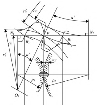
The root part of the tooth is most prone to pitting corrosion near the pitch line, so the contact stress at node P is taken as the basis for calculating the contact stress on the tooth surface. The simplified formula for calculating the contact strength of the tooth surface is as follows:

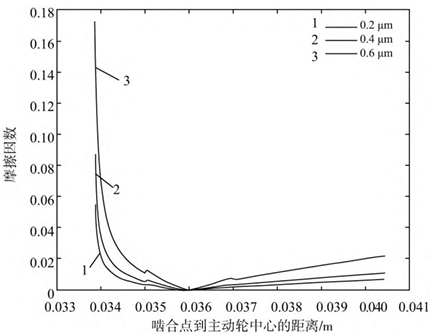
The time-varying friction coefficient formula obtained from a large number of experiments under the condition of elastohydrodynamic lubrication is shown in Figure 2 for tooth surface roughness of 0.2 μm, 0.4 μm, and 0.6 μm. The calculated friction coefficients are 0.014, 0.021, and 0.042, respectively, by calculating the root-mean-square value of the friction coefficient.
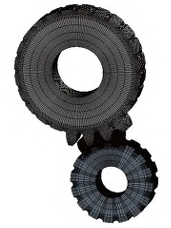
In Hypermesh, the tooth contact model is divided into hexahedral elements for mesh generation. The active wheel single tooth model has 239,646 nodes and 215,700 elements, while the active wheel base circle single tooth model has 4,900 nodes and 4,000 elements. The rotation replication is based on the tooth number and angle relationship (θ=360/z1), ensuring the accuracy of the calculated contact stress.
According to the gear meshing input-output relationship, if the load torque is 30000 Nmm, the input torque of the driving wheel is 20619 Nmm, which makes
Use joint-revolute to set the driving wheel as a single degree of freedom rotating joint, and joint-fixed to set the driven wheel as a fixed rotating joint.
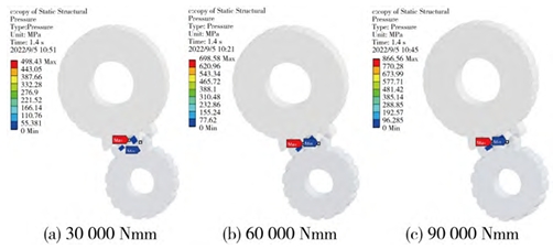
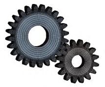
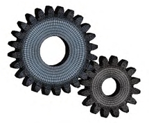
Through the static analysis of gear transmission in Ansys Workbench, the stress in the meshing area of gears during stable meshing transmission is studied
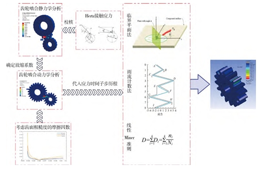
Strain characteristics are determined based on the load changes under transient dynamic loading cycles of gears and by comparing the load scaling factors. Under the SN fatigue (stress fatigue) module of the NCodE, the critical plane method and rainflow counting method are used to calculate the stress range and average stress, and combined with the Goodman equivalent life average stress correction, the final contact fatigue life prediction is performed using the Palmgren-Miner linear damage accumulation theory. The number of cycles and tooth surface areas at which failure occurs are obtained.
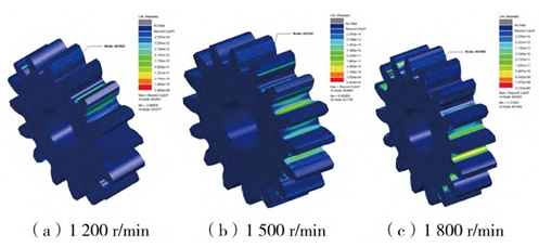
Analysis of contact fatigue life under different input speeds
The speed of the driving wheel was set to 1200r/min, 1500r/min, and 1800r/min, and the load torque of the driven wheel was set to 30000Nm. The transient dynamic analysis was performed to obtain the stress-time sub-step history of the gears. The results were then compared with the static analysis results of the load torque of 30000Nm, and the scaling factor was obtained. The contact fatigue life was calculated, and the fatigue life nephograms at 1200r/min, 1500r/min, and 1800r/min were obtained to analyze the driving wheel.
Set the load torque at the same speed of 2100r/min to be 30000Nm, 60000Nm, and 90000Nm, respectively, and perform transient dynamic analysis. Superimpose the respective statics comparisons, generate scaling factors, and obtain fatigue life cloud maps under different load torques, with the driving wheel as the main focus.
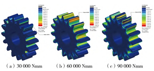
The greater the load torque, the smaller the number of gear cycles. This is because an increase in load torque increases the input torque, which in turn increases the contact stress. Compared with the analysis results in 3.1, it can be seen that: 1) the impact of load torque on contact fatigue life is much higher than that of input speed; 2) for the practical use of aviation gears, if you want to ensure a high working life under high-speed and heavy-load conditions, you need to replace materials with higher yield strength.
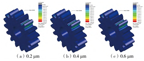
Conduct transient dynamic analysis of gears with the same speed of 1200r/min and the same load torque of 30000Nm, and set different tooth surface roughness of 0.2μm, 0.4μm, and 0.6μm to influence the friction coefficient for gear static analysis, obtain the corresponding load scaling factor, and obtain the fatigue life cloud map under different tooth surface roughness, mainly focusing on the driving wheel.
Epilogue
1) Establish a simulation model for gear contact fatigue life, and obtain the contact fatigue life and the most vulnerable damage nodes under different input speeds, load torques, and friction factors.
2) The influence law and magnitude of the three influencing factors on the contact fatigue life of the tooth surface were obtained. Through the prediction of the location of the critical nodes, it was found that damage is more likely to occur at both ends of the gear along the tooth width direction than at the middle position.
