spur bevel gears are usually formed by generating method on gear planer. On the basis of establishing the meshing coordinate system of spur bevel gear with installation error, a method is proposed to express the installation error sensitivity of the modified tooth surface of spur bevel gear by using the Gauss curvature of the difference surface on the two tooth surfaces in tangent contact at one point. The penalty function method is used to optimize the long axis of the contact ellipse, so as to obtain the footprint of the modified spur bevel gear with low sensitivity to installation error. The results show that the major axis of the contact ellipse has the greatest influence on the sensitivity coefficient of the tooth surface, and a better contact trace can be obtained by optimizing the major axis of the contact ellipse. When the contact trace is perpendicular to the root cone, the sensitivity of the installation error of the modified tooth surface of spur bevel gear can be reduced.
By establishing the meshing coordinate system of the spur bevel gear pair with installation error on the modified tooth surface of the spur bevel gear, the Gaussian curvature at the meshing point of the spur bevel gear pair is derived, and the value of the Gaussian curvature is used as an index to evaluate the sensitivity of the installation error of the modified tooth surface of the spur bevel gear. After analyzing the position of the reference point and the influence of the second-order contact parameters on the Gaussian curvature, the footprint map with low sensitivity to the installation error can be obtained by optimizing the long axis of the contact ellipse.
In order to improve the machining accuracy of bevel gears, a new method of digital roll inspection is proposed. Firstly, the cubic NURBS curve is studied, and the linear equations for solving the control vertices of NURBS curve are derived. Then a pair of spur bevel gear parameters are given from curve to surface, and the tooth surface is fitted by bicubic NURBS surface, and the influence of medium value points, node vectors and boundary conditions on fitting accuracy in the process of tooth surface reconstruction is analyzed. Finally, the fitting error is calculated. The analysis shows that the error is small, and the fitting tooth surface can be used to replace the real tooth surface. This method provides convenience for digital gear design and manufacture.
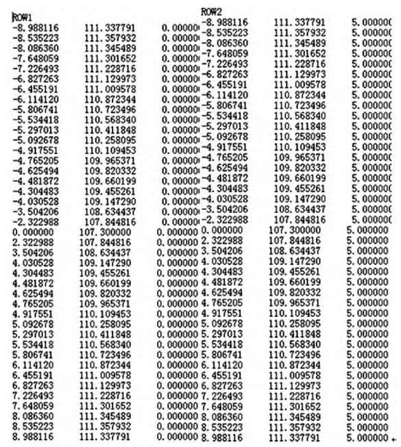
Based on the above theoretical research and the derivation of the theoretical contact area, a software for calculating the tooth surface points of spur bevel gears is developed by using Visual Basic language, as shown in Fig. 1. Only a few basic parameters of the spur bevel gear can be input to calculate the spatial tooth surface coordinates of the gear, and then the three-dimensional mathematical model can be established by importing UG software.
Taking the differential spur bevel gear of 58.9 ~ 66.2 kW wheel YTO Tractor as an example, the modeling is carried out. The power section differential is composed of two half shaft gears and two planetary gears. The main parameters of the gear pair are shown in Table 1.
| Project | Half shaft gear | Planet gear |
| Number of teeth / piece | 19 | 11 |
| Large end modulus / mm | 6.17 | 6.17 |
| Split cone angle / (°) | 59.93 | 30.07 |
| Top cone angle / (°) | 63.83 | 36.52 |
| Cone pitch / mm | 67.73 | 67.73 |
| Normal side clearance / mm | 0.18 | 0.18 |
| Pressure angle / (°) | 22.5 | 22.5 |
| Tooth width / mm | 23 | 26 |
| Chord tooth thickness at large end / mm | 8.64(0 -0.205) | 10.51(0 -0.19) |
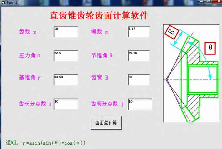
The tooth surface point data can be obtained by inputting the basic parameters of the half shaft gear with the compiled tooth surface point calculation software, as shown in Fig. 2.