
From my perspective, the spiral bevel gear is far more than a mechanical component. It is a compact expression of geometry, materials science, manufacturing precision, control theory, and economic decision-making. A spiral bevel gear transmits motion between intersecting shafts, often at 90 degrees, while providing smooth engagement, high load capacity, and relatively low noise. When I examine aircraft engines, automotive drivelines, marine propulsion systems, machine tools, and heavy equipment, I see the spiral bevel gear as a critical node where performance, reliability, and cost converge. I have therefore chosen to analyze its design and manufacturing status through a first-person lens, combining theory, process, equipment, quality control, challenges, and future directions. I use tables and formulas to make the relationships explicit, because the spiral bevel gear is a system problem rather than an isolated tooth profile.
My Starting Point: Why the Spiral Bevel Gear Matters
I begin with the functional role of the spiral bevel gear. Its curved teeth engage gradually, so the load moves across the tooth surface rather than striking suddenly. This gradual engagement reduces impact, distributes contact stress, and supports higher rotational speeds. In my assessment, the spiral bevel gear is especially valuable when the design must satisfy several contradictory goals at once: high torque density, low vibration, long fatigue life, compact packaging, and acceptable manufacturing cost. The spiral bevel gear is used in rotorcraft transmissions, automotive differentials, marine gears, industrial reducers, and precision machine tools. In each case, the spiral bevel gear must be designed as a three-dimensional surface, manufactured as a hardened precision body, measured as a functional pair, and validated as part of a dynamic system.
I do not treat design and manufacturing as separate stages. For the spiral bevel gear, design determines what can be manufactured, and manufacturing determines what the design actually becomes. A mathematically elegant tooth surface may be impossible to grind within tolerance. A highly capable five-axis machine may still produce a poor spiral bevel gear if the heat treatment distorts the tooth flank. I therefore use an integrated view: geometry, kinematics, tribology, thermal behavior, metrology, and economics must be considered together.
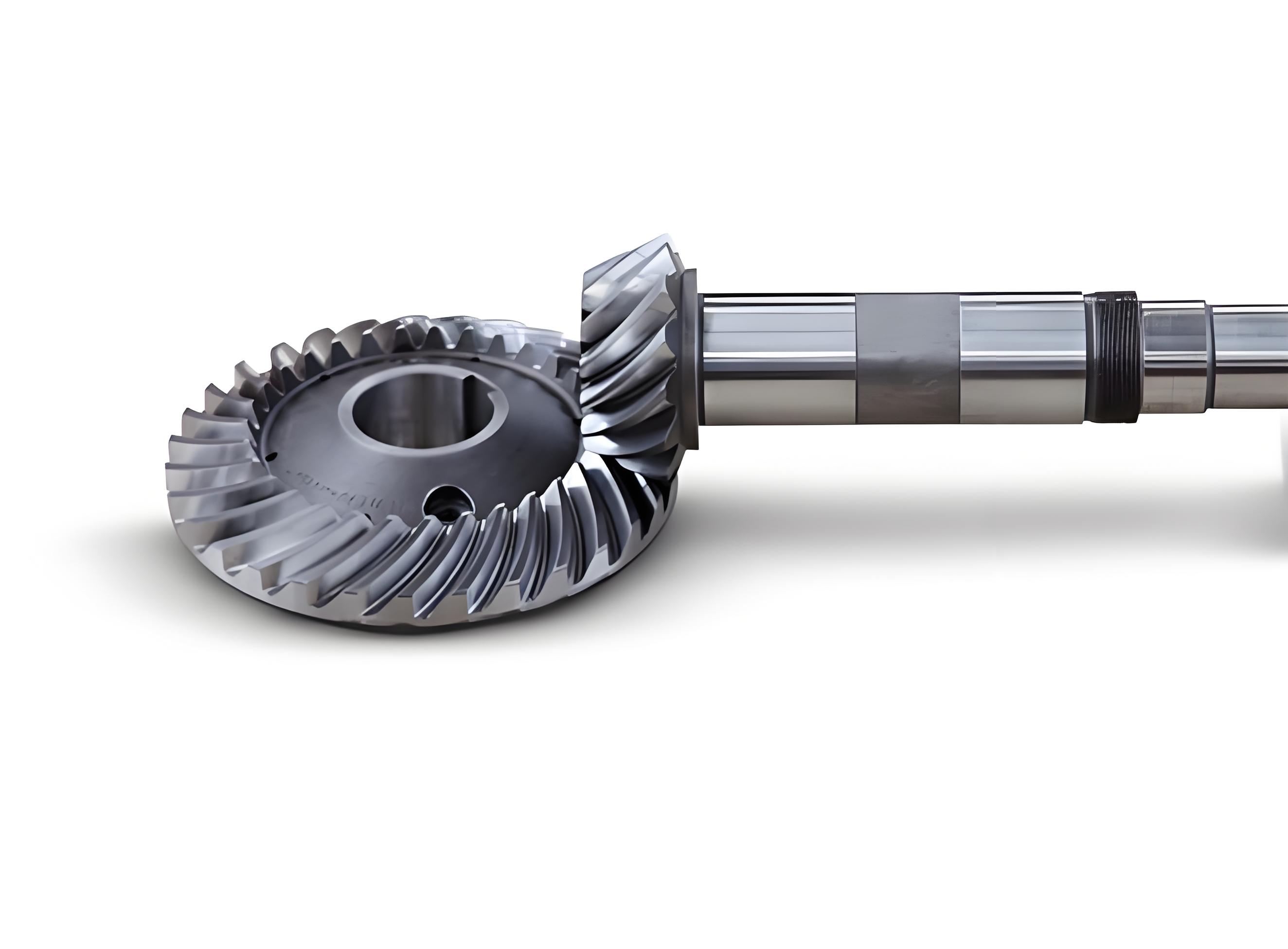
The Historical Arc of Spiral Bevel Gear Design Theory
When I trace the development of spiral bevel gear design theory, I see a movement from experience to analysis to computation to intelligence. Early practice relied on hand calculations, drafting, trial fitting, and craftsman knowledge. The designer could produce a working spiral bevel gear, but the process was slow and difficult to transfer. Later, geometry and mechanics provided formal tools for pitch cones, tooth thickness, pressure angle, spiral angle, and contact ratios. Computer-aided design and finite element analysis then allowed the spiral bevel gear to be modeled as a deformable contact system. Today, optimization, surrogate modeling, machine learning, and digital twins are entering the field. I summarize this arc in the following table.
| Era | Dominant Approach | Main Strength | Main Limitation for Spiral Bevel Gear |
|---|---|---|---|
| Empirical era | Workshop rules, templates, trial assembly | Practical and locally proven | Poor scalability and weak theoretical transfer |
| Analytical era | Geometry, kinematics, strength formulas | Provides systematic relationships | Simplifies contact, deformation, and thermal effects |
| CAD/CAE era | 3D modeling, finite element analysis, simulation | Predicts stress, contact, and transmission error | Depends heavily on model fidelity and boundary conditions |
| Optimization era | Parametric optimization, DOE, robust design | Balances multiple objectives | Can be computationally expensive |
| Intelligent era | AI, surrogate models, digital twins, data-driven control | Fast prediction and adaptive decisions | Requires high-quality data and validation |
I find that each era does not replace the previous one completely. A modern spiral bevel gear project still uses empirical rules for initial sizing, analytical formulas for feasibility, CAD/CAE for verification, optimization for refinement, and intelligent methods for monitoring and control. The key is not to choose one method but to connect them in a traceable workflow.
Geometric Foundations I Use for Spiral Bevel Gear Design
For a spiral bevel gear pair with shaft angle \(\Sigma\), numbers of teeth \(z_1\) and \(z_2\), and pitch cone angles \(\delta_1\) and \(\delta_2\), I begin with the fundamental relationships:
$$
\tan\delta_1 = \frac{\sin\Sigma}{\frac{z_2}{z_1}+\cos\Sigma}, \qquad
\tan\delta_2 = \frac{\sin\Sigma}{\frac{z_1}{z_2}+\cos\Sigma}
$$
For the common case \(\Sigma = 90^\circ\), these simplify to:
$$
\delta_1 = \arctan\frac{z_1}{z_2}, \qquad
\delta_2 = \arctan\frac{z_2}{z_1}
$$
The gear ratio of the spiral bevel gear pair is:
$$
i = \frac{n_1}{n_2} = \frac{z_2}{z_1}
$$
I use the cone distance \(R\), transverse module \(m_t\), and face width \(b\) as primary sizing variables. A common expression for cone distance is:
$$
R = \frac{m_t}{2}\sqrt{z_1^2+z_2^2}
$$
The face width of a spiral bevel gear is usually limited to control load distribution and avoid excessive end contact:
$$
b \le \frac{R}{3}
$$
When the normal module \(m_n\) and spiral angle \(\beta\) are used, I relate them through:
$$
m_n = m_t \cos\beta
$$
I also track addendum, dedendum, clearance, tooth thickness, and hand of spiral. For a spiral bevel gear, the hand of spiral must be matched between pinion and gear so that the axial forces are controlled. I summarize the key geometric variables in a compact table.
| Symbol | Meaning | Typical Design Concern |
|---|---|---|
| \(z_1, z_2\) | Pinion and gear tooth numbers | Ratio, undercut, sliding velocity |
| \(\Sigma\) | Shaft angle | Packaging and kinematics |
| \(\delta_1, \delta_2\) | Pitch cone angles | Axial positioning and contact pattern |
| \(m_t, m_n\) | Transverse and normal module | Strength and manufacturing tooling |
| \(\beta\) | Spiral angle | Overlap ratio, noise, axial force |
| \(b\) | Face width | Load capacity and edge contact |
| \(R\) | Cone distance | Size, stiffness, and blank design |
In my design practice, these equations are not merely calculations. They define the search space for the spiral bevel gear. If I choose a large spiral angle, I may improve overlap and smoothness, but I increase axial force and manufacturing sensitivity. If I choose a narrow face width, I reduce weight but reduce load capacity. If I choose a high gear ratio, I change the pitch cone angles and the sliding conditions. The spiral bevel gear is therefore a compromise surface, not a single optimum point.
Strength, Contact, and Transmission Error Models I Consider
I cannot evaluate a spiral bevel gear without strength and contact models. For contact stress, I often start with a Hertzian-type relationship adapted for bevel and hypoid gearing:
$$
\sigma_H = Z_E \sqrt{\frac{F_t}{b d_1}\frac{u+1}{u}K_A K_V K_{H\beta} K_{H\alpha}}
$$
Here \(F_t\) is tangential force, \(b\) is face width, \(d_1\) is pinion reference diameter, \(u\) is gear ratio, and the \(K\) factors account for application, dynamic, face load, and transverse load effects. For tooth root bending, I use a form related to the Lewis equation with bevel corrections:
$$
\sigma_F = \frac{F_t}{b m_n}Y_{Fa}Y_{Sa}Y_\beta K_A K_V K_{F\beta}K_{F\alpha}
$$
These formulas give me first-order guidance, but I never treat them as final for a spiral bevel gear. The actual contact is elliptical or ribbon-like, influenced by misalignment, crown, and edge relief. I therefore use finite element contact analysis and tooth contact analysis to predict load distribution. Transmission error is one of the most important dynamic indicators for a spiral bevel gear:
$$
TE(\phi) = \phi_{out}(\phi_{in}) – \frac{\phi_{in}}{i}
$$
I aim to minimize the peak-to-peak transmission error because it correlates with noise and vibration. In my view, a spiral bevel gear design that ignores transmission error may pass static strength checks yet fail in acoustic performance. I also monitor contact pattern under light and full load, because the pattern reveals whether the spiral bevel gear will concentrate stress at the toe, heel, top, or root.
| Performance Indicator | Physical Meaning | Design Lever | Manufacturing Sensitivity |
|---|---|---|---|
| Contact stress \(\sigma_H\) | Surface fatigue risk | Module, face width, profile radius | Grinding, lapping, alignment |
| Root stress \(\sigma_F\) | Bending fatigue risk | Tooth thickness, root fillet | Heat treatment, fillet finish |
| Transmission error \(TE\) | Motion irregularity | Crowning, spiral angle, contact ratio | Tooth flank form, runout |
| Contact pattern | Load distribution | Tooth surface modification | Set-up, lapping, assembly |
| Noise and vibration | System comfort and fatigue | TE, stiffness, damping | Surface roughness, balance |
How I Judge Existing Design Theory for Spiral Bevel Gear
Existing design theory has clear strengths. It gives me standardized equations, finite element workflows, optimization routines, and simulation environments. It allows a spiral bevel gear to be designed with far more confidence than in the empirical era. It also supports repeatability, traceability, and documentation. However, I see limitations. Many models still simplify material behavior, lubrication, thermal distortion, and assembly misalignment. A spiral bevel gear operates in a mixed elastohydrodynamic regime, and its tooth surface may experience scuffing, micropitting, and crack initiation that are not fully captured by static stress formulas. The theory also often treats the gear pair in isolation, while real systems include shafts, bearings, housings, and thermal growth. I therefore judge existing design theory as necessary but incomplete.
| Strength of Existing Design Theory | Limitation I Observe | My Practical Response |
|---|---|---|
| Mature geometry and strength formulas | Simplified boundary conditions | Use as screening, then simulate full system |
| CAD/CAE integration | Model fidelity depends on user assumptions | Validate with test data and TCA |
| Optimization capability | Multi-objective trade-offs can be opaque | Use robust design and sensitivity studies |
| Digital tools reduce design cycle | Data quality and interoperability issues | Build a traceable data pipeline |
| Supports complex tooth surfaces | Manufacturing constraints may be ignored early | Integrate DFM from the first iteration |
Manufacturing Processes I Compare for Spiral Bevel Gear Production
In manufacturing, I divide processes into traditional cutting and advanced manufacturing. Traditional cutting includes milling, hobbing-like generation, shaping, and grinding. Advanced methods include CNC generation, five-axis machining, laser-assisted processing, additive manufacturing, and precision forging. Each process has a different place in the spiral bevel gear lifecycle. For high-volume automotive differentials, forging and precision machining may dominate. For aerospace spiral bevel gears, grinding and lapping after heat treatment are often essential. For prototypes or complex internal features, additive manufacturing can shorten the cycle, but it may not yet match the fatigue performance of wrought and ground spiral bevel gears.
| Process | Typical Use for Spiral Bevel Gear | Advantages | Limitations |
|---|---|---|---|
| Milling and generation | Roughing and semi-finishing | Flexible, established | Tool wear, long cycle, setup sensitivity |
| Grinding | Hard finishing after heat treatment | High accuracy, good surface finish | Thermal damage risk, cost, wheel wear |
| Lapping | Matched pair correction | Improves contact pattern and noise | Manual skill, cycle time, limited material removal |
| Precision forging | High-volume near-net shape | Material savings, grain flow | Die cost, dimensional control |
| Additive manufacturing | Prototypes, complex cooling or lightweight forms | Design freedom, short lead time | Surface finish, residual stress, fatigue uncertainty |
| Laser-assisted machining | Difficult-to-cut materials | Reduced cutting force, improved tool life | Thermal control complexity |
When I analyze these processes, I use cost and quality models. A simple total cost model for a spiral bevel gear can be written as:
$$
C_{total} = C_{material} + C_{machining} + C_{tooling} + C_{heat treatment} + C_{inspection} + C_{logistics} + C_{environmental}
$$
I also estimate machining energy:
$$
E_{cut} = \int_0^T P_{cut}(t)\,dt
$$
For a spiral bevel gear, the manufacturing process is not just about removing material. It is about creating a hardened, aligned, and matched surface. I have found that the best design can be ruined by poor heat treatment control or by an unstable setup. Therefore, I treat process capability as a design constraint, not a downstream problem.
Equipment Choices and Their Influence on Spiral Bevel Gear Quality
Equipment selection shapes what I can achieve with a spiral bevel gear. Traditional machine tools are simple, robust, and inexpensive, but they rely on mechanical linkages and skilled operators. CNC machine tools provide programmable motion, repeatability, and compensation. Five-axis CNC machines are especially important for spiral bevel gear flanks because they can control tool orientation and position simultaneously. This capability allows crown, taper, and chamfer modifications that improve contact. Modern equipment also includes in-process probing, automatic tool changers, thermal compensation, and adaptive control.
| Equipment Type | Best Application | Quality Impact on Spiral Bevel Gear | Economic Impact |
|---|---|---|---|
| Conventional milling machine | Repair, simple gears, low volume | Moderate accuracy, operator dependent | Low capital, high labor |
| CNC gear generator | Batch production | Good repeatability | Moderate capital, lower cycle time |
| Five-axis machining center | Complex flank forms and prototypes | High geometric freedom | High capital, high flexibility |
| CNC grinding machine | Hard finishing of spiral bevel gear | High precision and surface quality | High cost, critical for aerospace |
| Lapping machine | Matched pair finishing | Improved contact pattern and noise | Labor and cycle cost |
| Metrology station | Inspection and feedback | Enables closed-loop correction | High value for quality assurance |
I believe the most important equipment trend is integration. A standalone machine can produce a good spiral bevel gear, but an integrated cell can measure it, compare it to the nominal surface, adjust the next cut, and document the result. This closed-loop approach reduces dependence on operator intuition. It also supports digital twins, because the machine data can be fed into a model of the spiral bevel gear process. In my view, the future of spiral bevel gear manufacturing is not only more axes or higher spindle speeds; it is more information flowing through the process.
Quality Control for Spiral Bevel Gear: From Design to Inspection
Quality control for a spiral bevel gear begins in design. I specify tooth geometry, material, heat treatment, surface finish, contact pattern, backlash, and runout. I then translate these requirements into process controls. During machining, I monitor tool wear, cutting force, temperature, and setup. After heat treatment, I check distortion and hardness. After grinding and lapping, I inspect tooth flank form, pitch, runout, and contact pattern. In my experience, the most effective quality system uses both variables data and attribute data. Variables data include dimensions and surface roughness. Attribute data include visual defects and contact pattern location.
I use process capability indices to judge whether a spiral bevel gear process is stable:
$$
C_p = \frac{USL – LSL}{6\sigma}, \qquad
C_{pk} = \min\left(\frac{USL-\mu}{3\sigma}, \frac{\mu-LSL}{3\sigma}\right)
$$
For surface finish, I may use the arithmetic mean roughness:
$$
R_a = \frac{1}{L}\int_0^L |z(x)|\,dx
$$
For tooth contact, I evaluate the contact pattern under light load and full load. A good spiral bevel gear contact pattern is not simply large; it must be correctly located and shaped. If the pattern is too close to the toe, the root may be overloaded. If it is too close to the heel, the tooth ends may chip. If it is too high or too low, the sliding conditions and bending stresses change. I therefore treat contact pattern as a functional signature of the spiral bevel gear pair.
| Quality Stage | Key Check | Typical Method | Risk If Neglected |
|---|---|---|---|
| Design review | Geometry, strength, TE target | Simulation, FEA, TCA | Systematic performance shortfall |
| Incoming material | Chemistry, hardenability, cleanliness | Spectroscopy, hardness, microstructure | Heat treatment variability, fatigue failure |
| Cutting and grinding | Tooth flank form, pitch, runout | CNC probing, gear measuring center | Noise, poor contact, premature wear |
| Heat treatment | Case depth, hardness, distortion | Hardness tester, metallography, CMM | Distortion, cracking, low load capacity |
| Lapping and assembly | Contact pattern, backlash | Marking compound, dial indicator | Edge contact, vibration, thermal failure |
| Final validation | Noise, vibration, temperature, life | Dynamometer, accelerometer, endurance rig | Field failure and warranty cost |
Technical Challenges I See for Spiral Bevel Gear Design and Manufacturing
The technical challenges are substantial. The spiral bevel gear has a complex tooth surface, and its contact is sensitive to small errors. A change of a few micrometers in flank form can move the contact pattern and change transmission error. The manufacturing process includes many coupled variables: tool geometry, machine kinematics, cutting parameters, heat treatment, grinding wheel wear, lapping, and assembly. In my view, the main technical challenge is not lack of individual tools but lack of integrated models that connect design intent to process output. I need models that can predict distortion, contact, and fatigue from the same set of physical assumptions.
| Technical Challenge | Why It Matters for Spiral Bevel Gear | Response I Recommend |
|---|---|---|
| Complex flank geometry | Small errors cause contact shift | Use high-fidelity TCA and closed-loop correction |
| Heat treatment distortion | Changes tooth form after cutting | Model distortion and compensate pre-grinding |
| Tool wear and wheel wear | Gradual loss of accuracy | In-process monitoring and adaptive compensation |
| Contact under load | Static pattern differs from running pattern | Use loaded TCA and system deflection analysis |
| Noise and transmission error | Acoustic and fatigue requirements tighten | Optimize micro-geometry and lapping strategy |
| Fatigue and surface durability | Safety-critical applications demand life prediction | Couple material, lubrication, and stress models |
I also see a data challenge. A spiral bevel gear generates geometry data, machine data, inspection data, and test data. If these data remain in separate silos, I cannot learn from them. If they are connected, I can improve design rules, compensate processes, and predict quality. The technical solution is therefore not only a new formula or machine; it is a data architecture for the spiral bevel gear lifecycle.
Economic Challenges for Spiral Bevel Gear Producers
Economically, I observe pressure from raw materials, energy, labor, tooling, and market volatility. A spiral bevel gear often requires alloy steel, heat treatment, precision grinding, and careful inspection. These steps consume energy and skilled labor. When material prices rise, the cost of the spiral bevel gear rises quickly. When demand fluctuates, capacity planning becomes difficult. When international trade changes, export-oriented producers face uncertainty. I therefore believe that cost control must be designed into the spiral bevel gear, not added after production.
| Economic Challenge | Effect on Spiral Bevel Gear | Mitigation I Prefer |
|---|---|---|
| Raw material price volatility | Higher blank and forging cost | Long-term supply agreements, near-net shape |
| Energy cost | Higher heat treatment and machining cost | High-efficiency motors, process optimization |
| Tooling cost | Grinding wheels and cutters wear rapidly | Tool life modeling and condition monitoring |
| Skilled labor shortage | Setup and lapping depend on experience | Automation, digital work instructions |
| Market fluctuation | Inventory and capacity mismatch | Flexible manufacturing and modular tooling |
| Quality failure cost | Warranty, downtime, and reputation loss | Robust design and statistical process control |
I use a simple economic objective when comparing spiral bevel gear alternatives:
$$
\min C_{life} = C_{acquisition} + C_{operation} + C_{maintenance} + C_{downtime} + C_{scrap}
$$
This life-cycle view is important because a cheaper spiral bevel gear may fail earlier and cost more in the field. For safety-critical systems, I would rather pay for a robust process than accept a low initial price with high uncertainty.
Environmental Challenges and My Sustainability Position
Environmental challenges are becoming central. A spiral bevel gear requires material extraction, forging or bar cutting, machining, heat treatment, grinding, cleaning, lubrication, and packaging. Each stage has energy use and emissions. I cannot claim that a spiral bevel gear is sustainable merely because it is efficient in service. I must evaluate the full life cycle. I use life cycle assessment thinking:
$$
EI = \sum_{s=1}^{N} \sum_{j} CF_j \cdot m_{s,j}
$$
Here \(EI\) is the environmental impact indicator, \(s\) indexes life-cycle stages, \(j\) indexes inventory flows, \(CF_j\) is the characterization factor, and \(m_{s,j}\) is the mass or energy flow. For a spiral bevel gear, the largest impacts often come from steel production, heat treatment, and grinding energy. I therefore look for cleaner electricity, higher material utilization, dry or minimum-quantity lubrication, and remanufacturing.
| Environmental Challenge | Impact of Spiral Bevel Gear Production | Sustainable Response |
|---|---|---|
| Material consumption | Steel and alloying elements | Near-net forging, additive repair, recycling |
| Energy consumption | Machining, grinding, heat treatment | Process optimization, waste heat recovery |
| Coolant and lubricant use | Fluid waste and mist | Minimum quantity lubrication, filtration |
| Emissions | Furnace and energy-related emissions | Clean electricity, efficient furnaces |
| Scrap and rework | Additional material and energy use | Closed-loop quality and compensation |
| End-of-life | Disposal or remanufacturing | Design for disassembly and refurbishment |
In my opinion, environmental performance should be treated as an engineering requirement for the spiral bevel gear, alongside strength and noise. A design that minimizes mass but requires excessive energy to manufacture may not be the best system solution. A process that reduces cycle time but increases scrap may not be sustainable. I therefore prefer multi-objective optimization that includes environmental impact.
Innovation Directions I Consider Most Promising
I see several innovation directions for the spiral bevel gear. First, digital design and simulation will become more integrated. A single model should support geometry, contact, stress, thermal, and manufacturing simulation. Second, advanced manufacturing will become more adaptive. Machines will measure the spiral bevel gear, compare it with the nominal model, and adjust the process. Third, new materials will enable higher power density. Fourth, intelligent monitoring will allow condition-based maintenance. Fifth, sustainability will drive process selection. I summarize these directions below.
| Innovation Direction | Expected Benefit for Spiral Bevel Gear | Key Enabler |
|---|---|---|
| Integrated digital design | Faster iteration and fewer physical trials | CAD/CAE/TCA platforms, digital twin |
| Adaptive CNC manufacturing | Higher accuracy and less scrap | In-process metrology, closed-loop control |
| Advanced materials | Higher load capacity and lower mass | Clean steels, composites, surface coatings |
| Additive and hybrid processes | Complex geometry and repair capability | Laser powder bed, directed energy deposition |
| Intelligent quality control | Earlier defect detection | AI vision, sensor fusion, statistical learning |
| Sustainable manufacturing | Lower energy and material waste | LCA, dry machining, energy monitoring |
I believe the most disruptive change will come from the combination of simulation and data. A spiral bevel gear is difficult to model exactly, but it generates abundant data during manufacturing and testing. If I can combine physics-based models with data-driven correction, I can achieve better accuracy than either approach alone. This hybrid approach is especially valuable for heat treatment distortion, which is difficult to predict from first principles for every batch.
Industry Trends I Expect to Shape the Spiral Bevel Gear Market
I expect industry trends to move in several directions. Electrification will change some automotive applications, but it will not eliminate the spiral bevel gear. Electric drive units still use reduction gearing, and many architectures use a spiral bevel gear or a similar bevel stage for differential or angle drive functions. Aerospace will continue to demand high reliability and lightweight spiral bevel gears. Wind energy and marine propulsion will demand larger, more durable spiral bevel gears. Industrial automation will demand quieter and more compact spiral bevel gears. At the same time, supply chains will become more regional and more digital.
| Industry Trend | Likely Effect on Spiral Bevel Gear | My Interpretation |
|---|---|---|
| Electrification | Different speed and load spectra | Noise and efficiency become more critical |
| Aerospace lightweighting | Higher power density | Advanced materials and topology optimization |
| Renewable energy | Large, reliable gearboxes | Fatigue life and maintenance access matter |
| Automation | Compact, precise drives | Transmission error and backlash control |
| Digital supply chains | Traceability and remote support | Digital thread for every spiral bevel gear |
| Sustainability regulation | Lower carbon footprint | LCA and energy-efficient processes |
I also expect a shift from product selling to performance assurance. Customers may not only buy a spiral bevel gear; they may buy a guaranteed contact pattern, a noise target, a life prediction, and a maintenance plan. This shift will require manufacturers to understand the entire system, not just the tooth geometry. It will also require better sensors and models for the spiral bevel gear in service.
New Materials and Processes for Future Spiral Bevel Gear Systems
Material development is a major lever for the spiral bevel gear. I look for high hardenability, fine grain size, low inclusion content, and good dimensional stability during heat treatment. Carburizing steels remain important, but I also see interest in nitriding, carbonitriding, and surface coatings. Lightweight materials such as high-strength aluminum or titanium are attractive for non-critical spiral bevel gears, but they often require surface treatment and careful design to handle contact stress. Composite materials can reduce mass, but their contact fatigue and thermal behavior must be proven. I summarize material directions in a table.
| Material Direction | Potential Benefit | Challenge for Spiral Bevel Gear |
|---|---|---|
| Clean alloy steel | Improved fatigue life | Cost and heat treatment control |
| Carburizing and nitriding steels | Hard case and tough core | Distortion and case depth uniformity |
| High-strength lightweight alloys | Mass reduction | Lower contact fatigue resistance |
| Surface coatings | Lower friction and wear | Adhesion and durability under load |
| Metal matrix composites | High stiffness and wear resistance | Machinability and cost |
| Additive alloys | Design freedom and repair | Porosity, residual stress, fatigue data |
For processes, I expect hybrid manufacturing to grow. A spiral bevel gear may be forged near-net, machined, heat treated, ground, and then laser-clad or peened in selected regions. Each process adds a capability. The challenge is to control the interfaces between processes. I believe the winning manufacturers will be those that can model the cumulative effect of every step on the final spiral bevel gear surface.
Intelligent and Automated Technologies for Spiral Bevel Gear
I see intelligent and automated technologies as essential for the future spiral bevel gear. Artificial intelligence can help with design space exploration, process parameter selection, and defect classification. Machine learning can build surrogate models that predict contact pattern or transmission error faster than full simulation. Digital twins can monitor a spiral bevel gear in service and estimate remaining life. Automation can reduce manual setup and lapping variability. However, I remain cautious: an AI model is only as good as its data and validation. For a safety-critical spiral bevel gear, I require physics-based verification and traceable evidence.
| Technology | Application to Spiral Bevel Gear | Value I See | Risk I Manage |
|---|---|---|---|
| AI design assistant | Parameter optimization and trade studies | Faster conceptual design | Overfitting and lack of physical insight |
| Surrogate modeling | Rapid prediction of stress and TE | Real-time optimization | Accuracy outside training domain |
| Machine vision | Contact pattern and surface defect inspection | Consistent quality decisions | Lighting and surface variability |
| Digital twin | Life prediction and maintenance planning | Reduced downtime | Model drift and sensor reliability |
| Adaptive control | Compensation for tool wear and distortion | Higher yield | Control stability and calibration |
| Robotic handling | Loading and unloading of spiral bevel gear blanks | Lower labor and higher safety | Flexibility and fixture cost |
In my view, the most practical near-term step is closed-loop metrology. If a machine can measure the spiral bevel gear after grinding and compare it to the nominal surface, it can adjust the next part. This does not require a fully autonomous factory. It requires a reliable measurement, a correction model, and a controlled process. Once that loop is stable, higher-level intelligence can be added.
Sustainability Strategies I Would Prioritize
For sustainability, I would prioritize three strategies. First, reduce material waste through near-net forging and additive repair. Second, reduce energy use through optimized cutting parameters, high-efficiency drives, and heat treatment scheduling. Third, reduce fluid waste through minimum quantity lubrication and proper filtration. I would also design the spiral bevel gear for remanufacturing where possible. A remanufactured spiral bevel gear can retain the expensive material and geometry while replacing only the worn surface. This approach saves energy and material compared with making a new part from scratch.
| Sustainability Strategy | Action for Spiral Bevel Gear | Expected Outcome |
|---|---|---|
| Material efficiency | Near-net shape, optimized blank, recycling | Less scrap and lower embodied energy |
| Energy efficiency | Process optimization, efficient motors, scheduling | Lower kWh per spiral bevel gear |
| Fluid reduction | Minimum quantity lubrication, dry grinding where possible | Less waste and mist |
| Remanufacturing | Grinding, lapping, recoating, retesting | Extended service life |
| Life cycle assessment | Measure impacts from cradle to grave | Evidence-based decisions |
| Digital documentation | Track material, process, and energy data | Transparent sustainability reporting |
I do not believe sustainability is optional for the spiral bevel gear industry. Regulations, customer requirements, and energy costs will make it a competitive factor. The manufacturers that can produce a high-quality spiral bevel gear with lower environmental impact will have an advantage. The key is to avoid trade-offs that simply shift the burden from one stage to another. A full life-cycle perspective is necessary.
My Integrated Framework for Spiral Bevel Gear Development
To manage the complexity, I use an integrated framework. I begin with requirements: torque, speed, ratio, life, noise, size, weight, cost, and environmental targets. I then create a preliminary spiral bevel gear geometry using classical equations. Next, I simulate contact, stress, and transmission error. I use optimization to adjust macro-geometry and micro-geometry. I then select materials and processes based on capability and cost. I design the manufacturing route, including cutting, heat treatment, grinding, lapping, and inspection. I validate the spiral bevel gear with tests and feed data back into the models. Finally, I monitor the product in service and use field data to improve future designs.
I can express the optimization problem in a general form:
$$
\min_{\mathbf{x}} F(\mathbf{x}) =
w_1 \frac{m(\mathbf{x})}{m_0} +
w_2 \frac{E_{TE}(\mathbf{x})}{E_{TE,0}} +
w_3 \frac{\sigma_H(\mathbf{x})}{\sigma_{H,0}} +
w_4 \frac{\sigma_F(\mathbf{x})}{\sigma_{F,0}} +
w_5 \frac{C(\mathbf{x})}{C_0} +
w_6 \frac{EI(\mathbf{x})}{EI_0}
$$
Subject to constraints such as:
$$
g_1(\mathbf{x}) = \sigma_H(\mathbf{x}) – \sigma_{H,allow} \le 0
$$
$$
g_2(\mathbf{x}) = \sigma_F(\mathbf{x}) – \sigma_{F,allow} \le 0
$$
$$
g_3(\mathbf{x}) = TE_{pp}(\mathbf{x}) – TE_{allow} \le 0
$$
$$
g_4(\mathbf{x}) = b(\mathbf{x}) – \frac{R(\mathbf{x})}{3} \le 0
$$
Here \(\mathbf{x}\) is the vector of design variables, including module, tooth numbers, spiral angle, face width, pressure angle, and modification parameters. The weights \(w_i\) reflect project priorities. For an aerospace spiral bevel gear, I may increase the weight on mass and reliability. For an automotive spiral bevel gear, I may increase the weight on cost and noise. For a renewable energy spiral bevel gear, I may increase the weight on fatigue life and maintainability. This framework helps me make trade-offs explicit rather than intuitive.
| Framework Stage | Input | Output | Decision I Make |
|---|---|---|---|
| Requirements | Load, speed, life, size, cost, environment | Target specification | Priority weights |
| Preliminary design | Ratio, shaft angle, module estimate | Pitch cone and blank geometry | Feasible concept |
| Simulation | 3D model, loads, boundary conditions | Stress, contact, TE | Geometry refinement |
| Optimization | Variables and constraints | Pareto set | Best compromise |
| Process design | Material and machine capability | Routing and parameters | Manufacturing plan |
| Validation | Test and inspection data | Correlation and correction | Release or iterate |
| Service feedback | Field data | Life and failure insights | Next-generation improvement |
Research Directions I Would Pursue Next
If I were to define a research agenda for the spiral bevel gear, I would focus on five areas. First, multi-scale modeling that connects microstructure, surface integrity, and contact fatigue. Second, real-time compensation for heat treatment distortion. Third, physics-informed machine learning for design and process optimization. Fourth, in-situ metrology and closed-loop manufacturing. Fifth, sustainable process chains with quantified environmental impact. These areas are not independent. They all rely on data, models, and validation.
| Research Direction | Core Question for Spiral Bevel Gear | Method | Expected Impact |
|---|---|---|---|
| Multi-scale fatigue modeling | How do microstructure and surface finish affect life? | Micromechanics, fatigue testing, simulation | More accurate life prediction |
| Distortion compensation | How can heat treatment distortion be predicted and reversed? | Thermo-mechanical simulation, metrology | Less scrap and shorter cycle |
| Physics-informed AI | Can data improve models without losing physical meaning? | Hybrid models, surrogate optimization | Faster and more reliable design |
| Closed-loop manufacturing | How can each spiral bevel gear be corrected in process? | In-situ probing, adaptive CNC | Higher quality and yield |
| Sustainable process chains | Which route minimizes life-cycle impact? | LCA, energy monitoring, optimization | Lower carbon and cost |
I also believe standardized data formats are needed. A spiral bevel gear project involves many software tools: CAD, CAE, CAM, metrology, and production control. If these tools cannot exchange data, the digital thread breaks. I would prioritize interoperability and traceability. Every spiral bevel gear should have a digital record that includes design intent, material certification, process parameters, inspection results, and service history. This record would support quality, warranty, and future design.
Concluding Perspective
From my first-person perspective, the spiral bevel gear remains a foundational component in advanced mechanical systems. Its design and manufacturing status shows remarkable progress, but it also reveals persistent challenges. I have examined the movement from empirical rules to analytical models, from manual machines to five-axis CNC systems, from isolated inspection to integrated quality control, and from cost-only decisions to life-cycle thinking. I have used formulas and tables to summarize geometry, strength, quality, economics, and sustainability. I have argued that the spiral bevel gear should be treated as an integrated system: design, material, process, equipment, inspection, and service must be connected. I have also argued that digitalization, intelligence, and sustainability will shape the next generation of spiral bevel gear technology.
In my judgment, the future spiral bevel gear will be designed with multi-objective optimization, manufactured with adaptive and closed-loop processes, inspected with high-resolution metrology, and monitored with digital twins. It will use advanced materials and coatings, and it will be produced with lower environmental impact. The companies and research groups that succeed will be those that can combine deep physical understanding with data-driven decision-making. The spiral bevel gear will not become obsolete; it will evolve. I expect it to remain a critical transmission element wherever high torque, compact packaging, and reliable angular motion are required. My conclusion is that the spiral bevel gear is both a mature technology and an open research field, and its next advances will come from integration rather than isolation.