
In the machining of eccentric shafts or eccentric sleeves, traditional methods often suffer from limited adaptability when dealing with multiple workpiece sizes or varying eccentricities. To address this challenge, we designed a novel stepless adjustable eccentric fixture that utilizes a worm gear transmission system to continuously vary the eccentric offset. The core innovation lies in the integration of a worm gear pair with a double eccentric wheel positioning mechanism, enabling infinite adjustment of the eccentricity without the need for discrete shims or manual recalibration. This article presents the working principle, kinematic analysis, design calculations, and practical advantages of the fixture, with particular emphasis on the role of the worm gear drive in achieving precise and smooth adjustments.
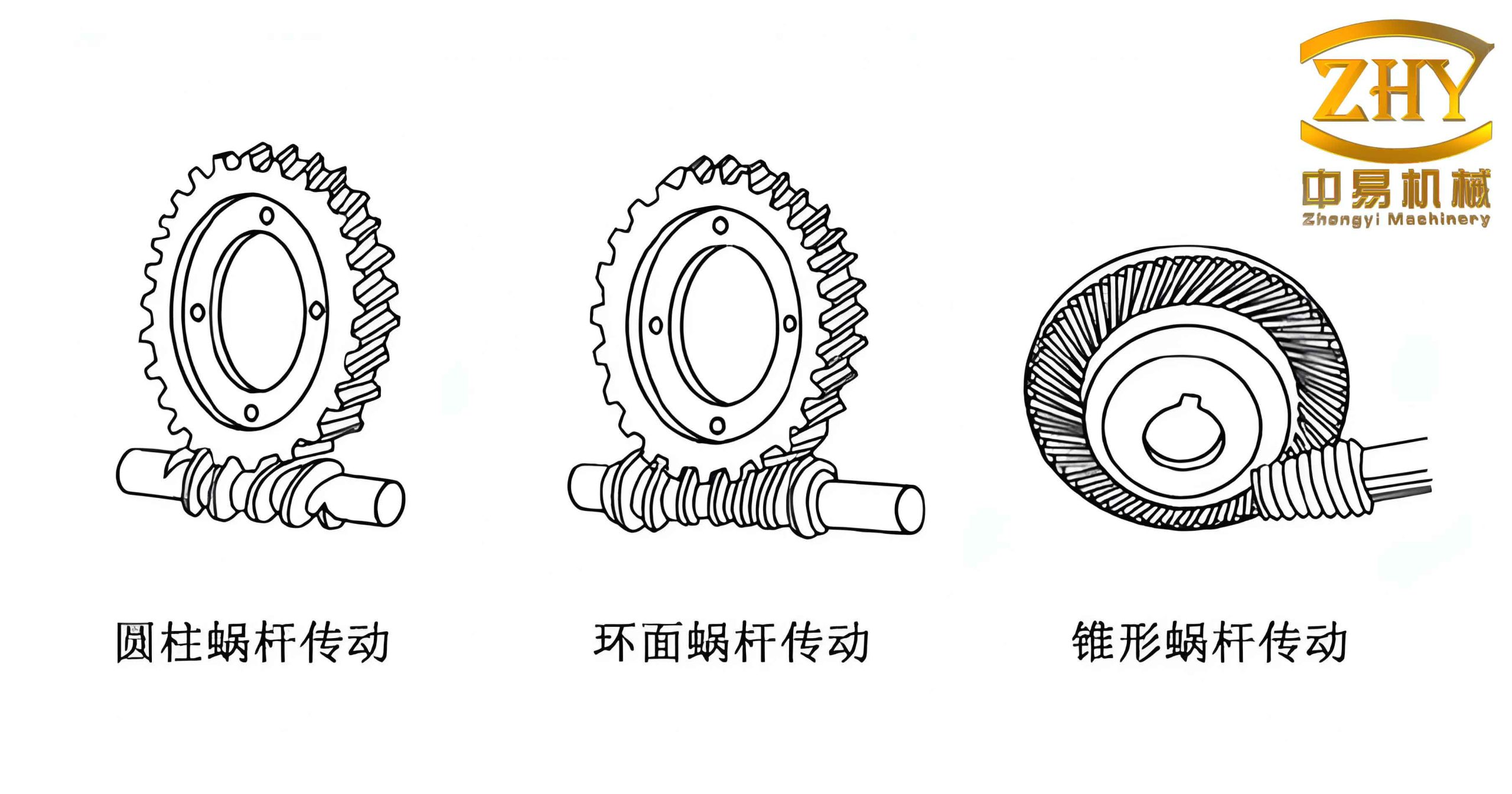
The figure above illustrates a typical worm gear set similar to the one employed in our fixture. The self-locking property of the worm gear transmission ensures that once the eccentricity is set, the mechanism remains stable under cutting forces, eliminating the need for additional locking devices in many applications. In the following sections, we detail the construction, parameter relationships, and mathematical derivations that underpin the design.
Design Principle and Component Overview
The fixture consists of two eccentric wheels that serve as the primary locating elements. Each eccentric wheel is rigidly connected to a worm wheel via a shaft. The worm wheels are driven by a common worm (or individual worms) that can be rotated manually or by a motor. The entire assembly is mounted on a fixture body through hinge pins, allowing the eccentric wheels to rotate about their respective hinge axes O₁ and O₂. The workpiece rests on the outer circular surfaces of the two eccentric wheels. By rotating the worm, the worm wheel rotates by a proportional angle determined by the gear ratio i. As a result, the orientation of the eccentric wheels changes continuously, altering the distance between the workpiece center and a fixed reference plane OA. This variation produces a continuously adjustable eccentricity e.
| Component | Symbol | Description |
|---|---|---|
| Eccentric wheel radius | R | Radius of the circular profile of each eccentric wheel |
| Eccentric wheel pivot radius | Rh | Distance from the hinge center to the center of the eccentric wheel |
| Workpiece radius | r | Radius of the cylindrical workpiece being machined |
| Distance between hinge centers | W | Center-to-center distance between O₁ and O₂ |
| Worm gear ratio | i | Ratio of worm wheel rotation angle to worm rotation angle (i = θwheel/θworm) |
| Initial angle of eccentric wheel | α₀ | Angle between the diameter through the pivot center and the reference plane OA when eccentricity is zero |
| Rotation angle of worm wheel | α | Angle by which the worm wheel turns from the initial position |
| Eccentricity | e | Offset between workpiece center and machine spindle center |
| Reference distance at zero eccentricity | M | Distance from workpiece center to reference plane OA when e = 0 |
| Variable distance at arbitrary α | H | Distance from workpiece center to reference plane OA after rotation by α |
The fixture can be designed to accommodate a range of workpiece diameters and eccentricity requirements. The worm gear drive offers the advantage of high reduction ratios, allowing fine resolution in angular positioning. Furthermore, the self-locking characteristic of the worm gear prevents undesired rotation during machining. Note that in practice, additional clamping elements (e.g., a lock nut on the worm shaft) may be incorporated for heavy-duty operations, though the worm gear itself provides adequate resistance for many applications.
Kinematic Analysis and Eccentricity Calculation
Figure 1 (conceptual diagram from the original work) shows the geometry of the double eccentric wheel mechanism. We define a fixed coordinate system with the reference plane OA as the datum. At the initial configuration (zero eccentricity), the workpiece center lies at a distance M below OA. This occurs when both eccentric wheels are oriented such that the diameter passing through their pivot centers makes an angle α₀ with OA. From the geometry, we have:
$$ M = \overline{AB} = \overline{O_1B} \sin\alpha_0 = (R – R_h + r) \sin\alpha_0 $$
When the worm wheel is rotated by an angle α (clockwise or counterclockwise), the eccentric wheel rotates correspondingly. The worm gear ratio i relates the worm rotation angle θ to the worm wheel angle α: α = θ / i (assuming the worm drives the wheel). For a single-start worm, i is the number of teeth on the worm wheel. By turning the worm, we can achieve any continuous value of α between 0 and 2π (or limited by mechanical stops).
We now derive the expression for the workpiece center position after a rotation α. Referring to Figure 2 (conceptual), we set up the following geometric relationships. Let O₁ be the left hinge center, O₂ the right hinge center. The distance between O₁ and O₂ is W. The eccentric wheel rotates about O₁ (and similarly O₂) such that the center of the eccentric wheel C moves on a circle of radius R_h around O₁. The point of contact between the eccentric wheel and the workpiece is denoted F, and the workpiece center is G. For simplicity, we assume both wheels are identical and equidistant from the workpiece, and that the workpiece is symmetric. The center G lies on the vertical line through the midpoint of O₁O₂ when e=0, but after rotation it may shift.
From triangle geometry (see original derivation), we obtain:
$$ \overline{CD} = R_h \cos(\alpha + \alpha_0) $$
$$ \overline{AE} = \overline{O_1D} = R_h \sin(\alpha + \alpha_0) $$
$$ \overline{CE} = \overline{CD} + \overline{DE} = R_h \cos(\alpha + \alpha_0) + \frac{W}{2} $$
$$ \overline{CG} = R + r $$
Applying the Pythagorean theorem in right triangle CEG:
$$ \overline{EG} = \sqrt{\overline{CG}^2 – \overline{CE}^2} = \sqrt{(R + r)^2 – \left[ R_h \cos(\alpha + \alpha_0) + \frac{W}{2} \right]^2} $$
The vertical distance from the reference plane OA to the workpiece center G is then:
$$ H = \overline{AG} = \overline{EG} – \overline{AE} = \sqrt{(R + r)^2 – \left[ R_h \cos(\alpha + \alpha_0) + \frac{W}{2} \right]^2} – R_h \sin(\alpha + \alpha_0) $$
Finally, the eccentricity e is the difference between H and the zero offset distance M:
$$ e = H – M = \sqrt{(R + r)^2 – \left[ R_h \cos(\alpha + \alpha_0) + \frac{W}{2} \right]^2} – R_h \sin(\alpha + \alpha_0) – (R – R_h + r) \sin\alpha_0 \quad (1) $$
Equation (1) is the fundamental relationship that governs the stepless adjustment of the eccentricity. All parameters except α are fixed during setup. By varying α continuously via the worm gear, we obtain a continuous range of e values. The worm gear allows fine increments; for example, with a worm wheel of 40 teeth, one full turn of the worm changes α by 9°, and a partial turn yields even finer steps.
| Parameter | Value | Unit |
|---|---|---|
| R | 30 | mm |
| Rh | 20 | mm |
| r | 25 | mm |
| W | 80 | mm |
| α₀ | 15 | deg |
| i (worm gear ratio) | 40 | – |
| M (computed) | (30-20+25)*sin15° = 35*0.2588 ≈ 9.059 | mm |
Using the values from Table 2, we can compute the eccentricity range. For α varying from -90° to +90° (limited by mechanical interference), we obtain a non-linear relationship. The maximum eccentricity occurs near α = -α₀ + some angle; the minimum occurs near α = 90° – α₀. Figure 3 (not shown) would illustrate the monotonic behavior. The worm gear drive ensures that the user can dial in any intermediate value quickly.
Design Considerations and Adjustment Range
The worm gear ratio i plays a crucial role in the resolution of the adjustment. Let Δθ be the smallest angular displacement of the worm that can be reliably achieved (e.g., by a handwheel with a vernier). The corresponding change in α is Δα = Δθ / i. The sensitivity of eccentricity to α is given by de/dα, which can be derived from equation (1). For small Δα, the change in eccentricity is Δe ≈ (de/dα) Δα. By selecting a sufficiently high gear ratio (e.g., i = 50 or 60), we can make Δe negligibly small, effectively achieving stepless adjustment.
Furthermore, the self-locking property of the worm gear ensures that the eccentric wheels remain fixed under dynamic loads. This is a significant advantage over friction-based clamping or manual locking mechanisms. In our prototype, we employed a single-start worm with a lead angle less than the friction angle, guaranteeing self-locking even under heavy cutting forces. For extremely high loads, an additional brake or lock nut on the worm shaft can be provided, but in typical machining operations, the worm gear alone suffices.
The fixture can also accommodate workpieces of different diameters by adjusting the initial position of the eccentric wheels. For a given nominal eccentricity, if the workpiece radius changes from r₁ to r₂, the required worm wheel rotation α can be recomputed using equation (1). In practice, a simple lookup table or a calibration chart can be created for quick setup. The worm gear drive makes this process straightforward because the user only needs to turn the worm to the appropriate angle indicated by a dial or digital readout.
Advantages and Applications
The proposed fixture offers several compelling benefits over conventional methods:
- Stepless adjustment: Unlike shim-based fixtures that require discrete step changes, the worm gear drive allows infinite variation of eccentricity within the design range.
- High resolution: With a large worm gear ratio, minute changes in eccentricity (on the order of microns) can be achieved.
- Self-locking: The worm gear transmission prevents accidental movement during machining, enhancing safety and precision.
- Universal applicability: The same fixture can handle a variety of eccentric shafts and sleeves without changing components. Only the worm gear rotation angle needs to be reset.
- Suitable for small batch production: In multi-variety, small-quantity manufacturing, the time saved in changeover is significant.
Potential applications include the machining of eccentric cams, offset crankshafts, eccentric bushings, and similar components in automotive, aerospace, and general machinery industries. The fixture can be mounted on lathes, grinding machines, or milling machines with appropriate adapters. The worm gear drive is particularly advantageous when high precision and repeatability are required.
Conclusion
We have presented a stepless adjustable eccentric fixture that leverages a worm gear transmission to achieve continuous variation of the workpiece offset. The kinematic model yields a closed-form expression for the eccentricity as a function of the worm wheel rotation angle. The self-locking property of the worm gear ensures stability during machining, while the high reduction ratio enables fine resolution. This design addresses the limitations of traditional fixed-eccentric fixtures and shim-based adjustments, making it ideal for modern flexible manufacturing environments. The worm gear drive is the enabling technology that transforms a conventional double eccentric wheel mechanism into a versatile, user-friendly, and precise tool for eccentric machining.
Future work may explore the integration of a digital encoder on the worm shaft for automated setting, as well as the optimization of the geometric parameters to maximize the eccentricity range while minimizing the required worm gear rotation. The worm gear’s efficiency and wear characteristics under repeated adjustments also warrant further study. Nevertheless, the current design demonstrates that a double eccentric wheel fixture driven by a worm gear can effectively meet the demands of small-batch, multi-variety eccentric part production.
| Method | Adjustment type | Resolution | Self-locking | Complexity | Cost |
|---|---|---|---|---|---|
| Shim packs | Discrete | Limited by shim thickness | No (requires separate clamping) | Low | Low |
| Manual eccentric collar with bolt | Discrete (indexed) | Coarse | Partial (friction) | Medium | Medium |
| Hydraulic eccentric actuator | Continuous | High | Yes (hydraulic lock) | High | High |
| Worm gear driven eccentric fixture | Continuous | Very high (fine) | Yes (inherent) | Medium | Moderate |
In summary, the worm gear-based stepless adjustable eccentric fixture represents a practical and efficient solution for machining eccentric parts with varying requirements. Its adoption in industrial settings can lead to reduced setup time, increased flexibility, and improved machining accuracy. We believe that this design will find widespread application in modern machine shops where adaptability and precision are paramount.