
The standard involute gear with 20 ° pressure angle processed by rack cutter is shown in the figure. The complete tooth profile between the tooth root circle and tooth top circle can be regarded as the combination of fillet transition curve shown in AB section and involute curve shown in BD section. Among them, the geometric shape of fillet transition curve AB is determined by the shape of gear shaper cutter during gear manufacturing. When the addendum fillet of gear shaper cutter is ordinary fillet, take driving gear P as an example, the curve of fillet transition curve AB can be described by Formula 1 in the xoy rectangular coordinate system shown in Figure 1. Similarly, the curve equation of BD segment of involute curve can be described by formula 2. As for the driven gear W, its tooth profile curve is similar to that of the driving gear P, which will not be repeated here.
Assuming that the spur gear tooth in the figure is subjected to the normal load f (gear meshing force) at the point pm on the tooth profile, the gear tooth can be approximately understood as the force analysis model of the variable cross-section beam. The energy method is used to deduce the energy work of the constant cross-section beam. For the variable cross-section beam model, the energy effect of the constant cross-section beam can be improved by the discrete micro element superposition method or the continuous integration form The improved function formula of gear load is as follows
According to the linear stiffness method, i.e. k = f / Δ x, the energy equation of the relationship between correlation and stiffness can be derived by substituting this equation into the formula, as shown in the formula. According to the load components FX = fsin (APM) and FY = fcos (APM) of the meshing force in the x-axis and Y-axis directions shown in Fig. 1, combined with the formula, the tooth stiffness ktoth composed of axial compression stiffness Ka, bending stiffness KB and shear stiffness KT can be derived. See the formula for the stiffness formula.

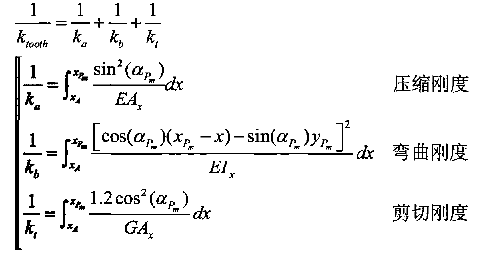
Where: APM working angle at meshing point, rad.