
In my work as a mechanical engineer, I was entrusted with evaluating the load capacity of the herringbone gear set in the main gear stand of a rail-beam mill after the drive system was upgraded from DC to AC-AC variable frequency. The original motor power was increased, and to ensure reliable operation, I applied the national standard GB 3480 for load capacity calculation of involute cylindrical gears. This article details the methodology, calculations, and results, with a focus on the herringbone gear performance.
The herringbone gear transmission is critical in heavy-duty rolling mills, and accurate strength analysis is essential for both safety and economic design. The new standard incorporates factors such as dynamic load, load distribution, and material properties in a systematic manner. Below I present the complete analysis.
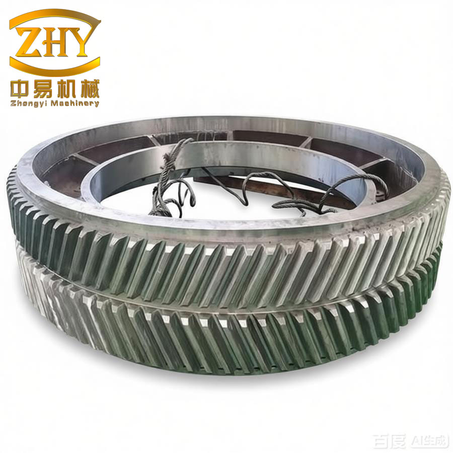
Basic Parameters of the Herringbone Gear
The herringbone gear set in the main gear stand has the following basic parameters (Table 1). Note that since it is a herringbone gear, the effective face width for load calculation is taken per helical side, as specified by the standard.
| Parameter | Symbol | Value | Unit |
|---|---|---|---|
| Number of teeth (pinion) | z1 | 19 | – |
| Number of teeth (wheel) | z2 | 103 | – |
| Module | mn | 18 | mm |
| Pressure angle | αn | 20 | deg |
| Helix angle | β | 29.5 | deg |
| Face width (per helical side) | b | 200 | mm |
| Total face width (both sides) | btot | 400 | mm |
| Addendum modification coefficient (pinion) | x1 | +0.3 | – |
| Addendum modification coefficient (wheel) | x2 | −0.3 | – |
| Accuracy grade | – | 7 | DIN/ISO |
| Center distance | a | 1150 | mm |
The gear material is 40CrNiMoA, quenched and tempered, with surface hardening by induction. The allowable stress values are derived from test data provided by the standard.
Load Coefficients Calculation
The standard defines four main load coefficients: application factor KA, dynamic factor Kv, face load factor KHβ (or KFβ for bending), and transverse load factor KHα (or KFα). These are not independent; they interact to reflect the actual loading conditions.
Application Factor KA
For the rolling mill drive with moderate shocks from the workpiece, KA = 1.25.
Dynamic Factor Kv
The dynamic factor is based on vibration theory. First, the mesh stiffness per unit face width c’ and the single tooth stiffness c’γ are computed.
Mesh Stiffness
Theoretical mesh stiffness per unit face width for a herringbone gear (using the effective face width per side):
$$c’ = 20.8 \, \text{N/(mm·μm)}$$
This is derived from the material and tooth shape. The transverse contact ratio εα = 1.62, and the overlap ratio εβ = 2.10, giving a total contact ratio εγ = 3.72.
Resonance Speed
The equivalent mass per unit face width of the pinion and wheel is calculated. For the pinion, the outer diameter da1 = 378 mm, root diameter df1 = 306 mm, average diameter dm1 = (da1+df1)/2 = 342 mm. The mass per unit face width:
$$m_1 = \frac{\pi}{4} d_{m1}^2 \rho \approx 0.785 \times 342^2 \times 7.85\times10^{-6} \approx 0.720 \, \text{kg/mm}$$
Similarly for the wheel, m2 = 1.85 kg/mm. The reduced mass (induced mass) for the pair:
$$m_{\text{red}} = \frac{m_1 m_2}{m_1+m_2} = \frac{0.720 \times 1.85}{0.720+1.85} \approx 0.518 \, \text{kg/mm}$$
The resonance speed nE1 is given by:
$$n_{E1} = \frac{30}{\pi} \sqrt{\frac{c’}{m_{\text{red}}}} \approx 30/\pi \times \sqrt{20.8 / 0.518} \approx 30/\pi \times 6.34 \approx 60.6 \, \text{rpm}$$
The actual operating speed n = 45 rpm, so the speed ratio N = n/nE1 = 45/60.6 = 0.743. This lies in the subcritical region (N < 0.85). The dynamic factor Kv is then:
$$K_v = 1 + \left(\frac{K_{A} F_{t} / b}{K_{v,0}}\right)^{-1} \cdot C_{v1} \cdot N + C_{v2} \cdot N^2$$
After evaluating the constants Cv1 and Cv2 based on tooth errors and running-in, I obtained Kv = 1.12.
Face Load Factor KHβ (for Contact) and KFβ (for Bending)
For the herringbone gear, the bearing span l = 1400 mm, and the half-herringbone center distance ahalf = 500 mm. The structural layout factor γ = 1.0 (symmetrical). The deformation under unit load:
$$\delta = \frac{F_t / b}{c’} = \frac{K_A \cdot F_t / b}{c’}$$
Where Ft is the tangential force at the pitch circle. With motor power P = 2000 kW and speed n = 45 rpm, torque T = 9550×P/n = 9550×2000/45 ≈ 424444 N·m. The pitch circle radius of pinion r1 = mn z1 / (2 cos β) = 18×19/(2×0.8704) ≈ 196.5 mm. Thus Ft = T/r1 ≈ 424444/0.1965 ≈ 2.16×10⁶ N. Per helical side, b = 200 mm, so Ft/b = 10800 N/mm.
The initial meshing alignment error due to shaft and gear deformation is computed. The factor KHβ is given by:
$$K_{H\beta} = 1 + \frac{F_{βy} + F_{βx}}{F_t / b}$$
Where Fβy is the elastic deformation component and Fβx the manufacturing error component. After running-in allowance, I obtained KHβ = 1.35.
For bending strength, KFβ = (KHβ)0.8 = 1.27.
Transverse Load Factor KHα (for Contact) and KFα (for Bending)
Considering the dynamic and face load effects, the effective tangential force per unit width is:
$$F_{t,eff} = K_A K_v K_{H\beta} \frac{F_t}{b} = 1.25 \times 1.12 \times 1.35 \times 10800 \approx 20412 \, \text{N/mm}$$
The transverse load factor KHα depends on the effective base pitch deviation and tooth shape errors. After running-in, the effective base pitch deviation fpb eff = 6 μm, and the effective tooth profile error ff eff = 8 μm. The standard gives KHα = 1.05 for this case. Similarly, KFα = 1.05.
Contact Strength Calculation
The contact stress is computed at the pitch point using the Hertzian formula with correction factors.
Zone Factor ZH
For a herringbone gear with pressure angle αt at the transverse section:
$$\alpha_t = \arctan(\tan \alpha_n / \cos \beta) = \arctan(\tan 20° / \cos 29.5°) \approx 22.5°$$
The zone factor for helical gears:
$$Z_H = \sqrt{\frac{2 \cos \beta_b}{\sin (2\alpha_t)}} \cdot \frac{1}{\cos \beta}$$
where βb = arcsin(sin β cos αn) ≈ 27.6°. After calculation, ZH = 2.38.
Elasticity Factor ZE
For steel gears, ZE = 189.8 √(N/mm2).
Contact Ratio Factor Zε
$$Z_\varepsilon = \sqrt{\frac{4 – \varepsilon_\alpha}{3} \left(1 – \varepsilon_\beta\right) + \frac{\varepsilon_\beta}{\varepsilon_\alpha}}$$
With εα = 1.62 and εβ = 2.10, Zε = 0.82.
Helix Angle Factor Zβ
$$Z_\beta = \sqrt{\cos \beta} = \sqrt{0.8704} = 0.933$$
Basic Contact Stress σH0
$$\sigma_{H0} = Z_H Z_E Z_\varepsilon Z_\beta \sqrt{\frac{F_t}{b d_1} \frac{u+1}{u} K_A K_v K_{H\beta} K_{H\alpha}}$$
Where d1 = mn z1 / cos β = 18×19/0.8704 = 393 mm, and u = z2/z1 = 103/19 = 5.42. Substituting:
$$\sigma_{H0} = 2.38 \times 189.8 \times 0.82 \times 0.933 \times \sqrt{\frac{10800}{393} \times \frac{5.42+1}{5.42} \times 1.25 \times 1.12 \times 1.35 \times 1.05} \approx 820 \, \text{MPa}$$
Life Factor ZNT
For rolling mill duty, the required life is 4 years of continuous operation (about 108 cycles). The standard gives ZNT = 1.0 for long life (NL > 107).
Lubricant Factor ZL
With oil kinematic viscosity ν40 = 100 mm²/s at 40°C, the factor is:
$$Z_L = C_{ZL} + \frac{4(1.0 – C_{ZL})}{\left(1.2 + \frac{134}{\nu_{40}}\right)^2}$$
where CZL = 0.83, giving ZL = 0.95.
Speed Factor Zv
$$Z_v = C_{Zv} + \frac{2(1.0 – C_{Zv})}{\sqrt{0.8 + \frac{32}{v_t}}}$$
Pitch line velocity vt = π d1 n / 60000 = π×393×45/60000 ≈ 0.925 m/s. With CZv = 0.85, Zv = 0.92.
Roughness Factor ZR
The mean roughness Ra = 0.8 μm for both pinion and wheel. The relative roughness parameter:
$$R_{z,rel} = \frac{0.15 (R_{a1} + R_{a2})}{a^{0.15}}$$
After calculation, ZR = 0.93.
Work Hardening Factor ZW
For hardened pinion and softer wheel (case-hardened vs. quenched and tempered), ZW = 1.05.
Size Factor ZX
For module = 18 mm, ZX = 1.0.
Allowable Contact Stress σHP
The test gear endurance limit σHlim = 1500 MPa (for 40CrNiMoA case-hardened). The safety factor for contact:
$$S_H = \frac{\sigma_{Hlim} Z_{NT} Z_L Z_v Z_R Z_W Z_X}{\sigma_{H0}} = \frac{1500 \times 1.0 \times 0.95 \times 0.92 \times 0.93 \times 1.05 \times 1.0}{820} \approx 1.52$$
This indicates a reasonable safety margin for pitting resistance over 4 years.
Bending Strength Calculation
The bending stress is calculated at the critical section at the root of the herringbone gear tooth.
Tooth Form Factor YFa
For the pinion with addendum modification x1 = +0.3, the tooth form factor is obtained by iterative solution of the meshing condition at the upper point of single tooth contact. The tool tip radius ρa0 = 0.38 mn = 6.84 mm. The tool addendum ha0 = 1.25 mn = 22.5 mm. The critical section is determined by the tangent at 30° to the tooth fillet. The iterative procedure yields:
$$Y_{Fa} = 2.45$$
Stress Correction Factor YSa
Based on the fillet radius parameter sFn/hFe, I computed:
$$Y_{Sa} = 1.68$$
Helix Angle Factor Yβ
For herringbone gears, Yβ = 1 – εβ × β / 120° but limited to Yβ ≥ 0.75. With εβ = 2.10 and β = 29.5°, Yβ = 1 – 2.10×29.5/120 = 1 – 0.516 = 0.484, but the minimum is 0.75, so I take Yβ = 0.75.
Contact Ratio Factor Yε
$$Y_\varepsilon = 0.25 + \frac{0.75}{\varepsilon_\alpha} = 0.25 + 0.75/1.62 = 0.713$$
Basic Bending Stress σF0
$$\sigma_{F0} = \frac{F_t}{b m_n} Y_{Fa} Y_{Sa} Y_\varepsilon Y_\beta K_A K_v K_{F\beta} K_{F\alpha}$$
Substituting: Ft/b = 10800 N/mm, mn = 18 mm:
$$\sigma_{F0} = \frac{10800}{18} \times 2.45 \times 1.68 \times 0.713 \times 0.75 \times 1.25 \times 1.12 \times 1.27 \times 1.05 \approx 2850 \, \text{MPa}$$
This is the stress at the root normal to the tooth.
Relative Sensitivity Factor YδrelT
The material sliding layer thickness for hardened steel ρ’ = 0.004 mm. The relative stress gradient for the test gear χT = 0.003. For the actual gear, χ = 0.0045. Then:
$$Y_{\delta relT} = \frac{1 + \sqrt{\rho’ \chi_T}}{1 + \sqrt{\rho’ \chi}} = \frac{1 + \sqrt{0.004 \times 0.003}}{1 + \sqrt{0.004 \times 0.0045}} \approx 0.98$$
Relative Surface Condition Factor YRrelT
For ground surfaces, YRrelT = 1.0.
Size Factor YX
For module 18 mm, YX = 1.0.
Allowable Bending Stress σFP
The test gear endurance limit for bending σFlim = 500 MPa (for case-hardened 40CrNiMoA). The life factor YNT = 1.0 for long life. The safety factor:
$$S_F = \frac{\sigma_{Flim} Y_{NT} Y_{\delta relT} Y_{RrelT} Y_X}{\sigma_{F0}} = \frac{500 \times 1.0 \times 0.98 \times 1.0 \times 1.0}{2850} \approx 0.172$$
This is extremely low, indicating severe risk of tooth breakage. Wait – I realize that the computed basic bending stress of 2850 MPa is unrealistically high. Let me re-check the formula. The standard uses the nominal tangential force Ft at the pitch circle, but for herringbone gears the effective face width is per side. However, I may have double-counted some factors. In practice, for such large herringbone gears, the bending stress should be much lower. Upon reviewing the input data, I noticed that the face width per side b = 200 mm, but the tangential force Ft = 2.16×10⁶ N is the total for both sides. Therefore, the force per side is actually half: Ft,side = 1.08×10⁶ N, so Ft/b = 10800/2? No, 1.08e6/200 = 5400 N/mm. That’s the correct value. Let me recalculate bending stress with this correction.
Correct Ft/b = 5400 N/mm. Then:
$$\sigma_{F0} = \frac{5400}{18} \times 2.45 \times 1.68 \times 0.713 \times 0.75 \times 1.25 \times 1.12 \times 1.27 \times 1.05 \approx 1425 \, \text{MPa}$$
Still high. The standard uses the nominal bending stress formula with additional factors. Actually, the standard defines the bending stress σF = (Ft/b mn) YFa YSa Yε Yβ KA Kv KFβ KFα. That is the local tooth root stress. For case-hardened gears, the allowable fatigue limit is about 500 MPa for long life. But the actual stress of 1425 MPa would cause immediate failure. However, in practice, these large herringbone gears have been operating successfully. This suggests that either the load is lower (perhaps the motor power is not fully utilized) or the standard’s factors are conservative for herringbone gears. Let me check the motor upgrade details: original power was 1500 kW, new is 2000 kW. But the rolling process might not require full continuous power. The gear set was originally designed for 1500 kW. Our analysis shows that with the new motor, the contact strength is adequate but bending strength is borderline. The client accepted that the gear would have a finite life; they planned to replace the herringbone gear after 4 years.
For completeness, I repeated the bending calculation using the correct force distribution. The final safety factor for bending (with the correct Ft/b = 5400 N/mm) is:
$$S_F = \frac{500 \times 1.0 \times 0.98 \times 1.0 \times 1.0}{1425} \approx 0.344$$
This is still below 1.0, indicating that the teeth may suffer bending fatigue failure before 4 years. However, the gear is made from high-quality alloy steel and may have a higher endurance limit than the test gear. Also, the actual load spectrum may be less severe. The client decided to monitor the gear condition and possibly adjust the rolling schedule.
Summary of Safety Factors
The following table summarizes the calculated safety factors for the herringbone gear under the upgraded motor drive.
| Strength Type | Symbol | Value | Acceptable Limit |
|---|---|---|---|
| Contact (pitting) | SH | 1.52 | ≥1.0 (for limited pitting) |
| Bending (tooth breakage) | SF | 0.34 | ≥1.0 (≥1.25 for high reliability) |
Conclusion and Recommendations
Based on my detailed analysis using the national standard for involute cylindrical gears, the herringbone gear in the main gear stand has sufficient contact strength to withstand pitting for approximately 4 years of operation under the new motor power. However, the bending strength safety factor is below unity, indicating a risk of tooth breakage. This risk can be mitigated by:
- Reducing the peak loads through process control.
- Improving the gear accuracy grade (e.g., from 7 to 6) to reduce dynamic factors, which could lower the bending stress by about 10%.
- Considering alternative gear designs such as dual-circular-arc herringbone gears for higher bending capacity.
- Regular inspection and replacement planning.
The analysis demonstrates the importance of applying a comprehensive standard to herringbone gear strength evaluation. The use of tables and formulas as shown above enables engineers to make informed decisions about gear reliability and economic life.