
In my experience as a mechanical engineer specializing in gear design, I have found that hypoid bevel gears are critical components in automotive drive axles, offering smooth operation and high load capacity. The strength calculation of these gears involves complex interactions between geometry, material properties, and operating conditions. Here, I will present a comprehensive overview of the bending and contact strength calculation methods for hypoid bevel gears, drawing from established engineering practices. I will use formulas and tables to summarize key parameters, ensuring that the discussion is both practical and detailed. Throughout this article, I will emphasize the importance of proper design considerations for hypoid bevel gears to achieve optimal performance and durability.
The fundamental approach to analyzing hypoid bevel gears starts with determining the applied torque. Unlike simplistic methods, I recommend considering daily driving torque, engine maximum torque, and wheel slip torque to account for real-world conditions. The daily driving torque, also known as performance torque, incorporates factors such as road gradient, rolling resistance, and acceleration inertia. It can be calculated using the following formula: $$ T_d = \frac{W \cdot r \cdot (G + R + P)}{i_t \cdot \eta} $$ where \( T_d \) is the torque on the ring gear shaft in N·m, \( W \) is the total vehicle weight in kg, \( r \) is the tire rolling radius in m, \( G \) is the grade coefficient (as a percentage), \( R \) is the rolling resistance coefficient (as a percentage), \( P \) is the performance coefficient (as a percentage), \( i_t \) is the total gear ratio from the ring gear to the wheel, and \( \eta \) is the driveline efficiency (typically 0.9 for highway vehicles). The grade coefficient depends on vehicle type, as shown in Table 1, while rolling resistance coefficients vary with road surface, as summarized in Table 2.
| Vehicle Type | Grade Coefficient \( G \) (%) |
|---|---|
| Passenger Cars | 10 |
| US Trucks | 8 |
| Other Country Trucks | 12 |
| City Buses | 8 |
| Long-Distance Buses | 8 |
| Off-Road Vehicles | 15 |
| Military Vehicles | 20 |
| Road Surface Type | Good Surface \( R \) (%) | Average Surface \( R \) (%) | Poor Surface \( R \) (%) |
|---|---|---|---|
| Concrete | 1.0 | 1.5 | 2.0 |
| Asphalt | 1.2 | 1.7 | 2.2 |
| Gravel | 2.5 | 3.5 | 4.5 |
| Dirt | 3.0 | 4.0 | 5.0 |
For engine maximum torque, I use: $$ T_e = \frac{T_{eng} \cdot K_c \cdot i_1 \cdot i_0 \cdot \eta}{n} $$ where \( T_e \) is the torque on the ring gear shaft in N·m, \( T_{eng} \) is the engine maximum net output torque in N·m, \( K_c \) is the overload factor due to clutch engagement (e.g., 1.0 for automatic transmissions, 1.2 for manual transmissions), \( i_1 \) is the first gear ratio, \( i_0 \) is the axle ratio, \( \eta \) is the transmission efficiency (typically 0.9), and \( n \) is the number of driving axles. For wheel slip torque, I apply: $$ T_s = \frac{W_a \cdot \mu \cdot r}{i_t \cdot \eta_d} $$ where \( T_s \) is the torque on the ring gear shaft in N·m, \( W_a \) is the load on the driving axle in kg, \( \mu \) is the adhesion coefficient (e.g., 0.8 for good roads, 1.0 for off-road), and \( \eta_d \) is the efficiency from ring gear to wheel (typically 0.95). The design torque for hypoid bevel gears is the smaller of \( T_e \) and \( T_s \), while daily driving torque is used for endurance limits.
When calculating bending stress for hypoid bevel gears, I differentiate between the ring gear and pinion due to their distinct geometries. The bending stress for the ring gear is given by: $$ \sigma_{b2} = \frac{T_2 \cdot K_o \cdot K_v}{b_2 \cdot m_t \cdot K_s \cdot K_m} \cdot Y_2 $$ where \( \sigma_{b2} \) is the bending stress at the root of the ring gear tooth in MPa, \( T_2 \) is the torque on the ring gear shaft in N·m, \( K_o \) is the overload factor, \( K_v \) is the dynamic factor, \( b_2 \) is the face width of the ring gear in mm, \( m_t \) is the transverse module at the large end in mm, \( K_s \) is the size factor, \( K_m \) is the load distribution factor, and \( Y_2 \) is the geometry factor for bending strength of the ring gear. For the pinion, I use: $$ \sigma_{b1} = \frac{T_1 \cdot K_o \cdot K_v}{b_1 \cdot m_t \cdot K_s \cdot K_m} \cdot Y_1 $$ or alternatively, if the pinion face width \( b_1 \) is unknown, I apply: $$ \sigma_{b1} = \sigma_{b2} \cdot \frac{Y_1}{Y_2} \cdot \frac{b_2}{b_1} $$ Here, \( T_1 \) is the torque on the pinion shaft in N·m, calculated as \( T_1 = T_2 / i \) where \( i \) is the gear ratio, and \( Y_1 \) is the geometry factor for the pinion. These formulas highlight the need for precise geometry factors in hypoid bevel gears design.
Contact stress, which is critical for surface durability, is identical for both gears in a hypoid bevel gear pair. I compute it using: $$ \sigma_c = C_p \sqrt{ \frac{T_1 \cdot K_o \cdot K_v}{b \cdot d_1} \cdot \frac{I}{K_s \cdot K_m \cdot C_f} } $$ where \( \sigma_c \) is the maximum contact stress in MPa, \( C_p \) is the elastic coefficient in \( \sqrt{\text{MPa}} \), \( d_1 \) is the pitch diameter of the pinion at the large end in mm, \( I \) is the geometry factor for contact strength, and \( C_f \) is the surface condition factor. The elastic coefficient for steel hypoid bevel gears is typically 191 \( \sqrt{\text{MPa}} \), derived from: $$ C_p = \sqrt{ \frac{\pi}{\left( \frac{1 – \nu_1^2}{E_1} + \frac{1 – \nu_2^2}{E_2} \right) } } $$ with \( \nu = 0.3 \) and \( E = 2.07 \times 10^5 \) MPa for steel.
In practice, I rely on various coefficients to adjust these stresses for real-world conditions. The overload factor \( K_o \) accounts for engine and driven machinery irregularities; I select it based on application, as shown in Table 3. For hypoid bevel gears in passenger cars, I often use \( K_o = 1.0 \). The dynamic factor \( K_v \) reflects tooth errors and vibrations; for high-quality gears with AGMA class 9 or better, I take \( K_v = 1.0 \), but for lower precision, I refer to curves relating pitch line velocity to \( K_v \), as illustrated in Figure 1. Since I cannot include images directly, I will insert a reference to a visual representation of hypoid bevel gears here to aid understanding:
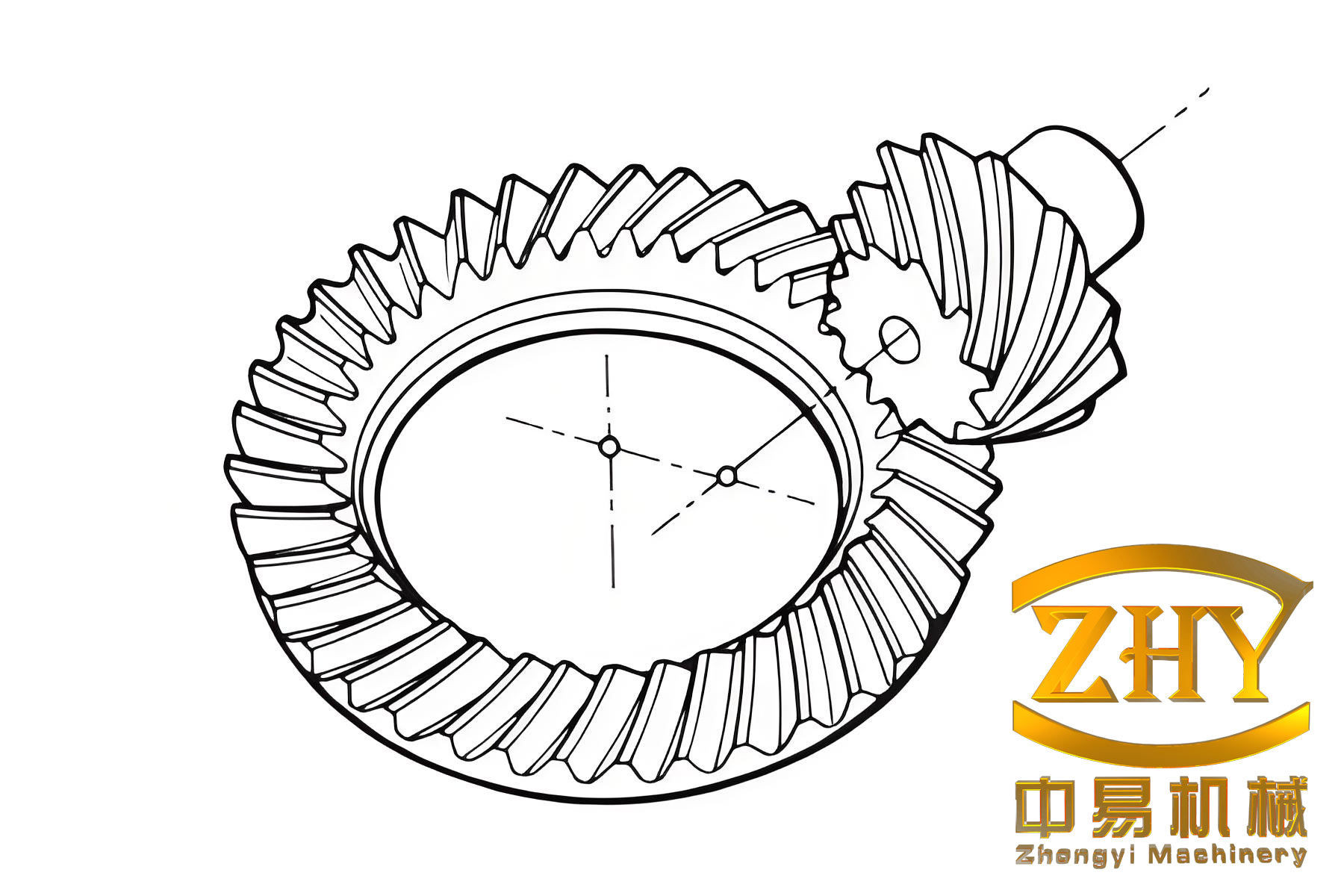
This image shows typical hypoid bevel gears geometry, which influences factors like spiral angle and offset.
| Application | Overload Factor \( K_o \) |
|---|---|
| Uniform Motor and Driven Machine | 1.00 |
| Light Shock (e.g., Passenger Cars) | 1.25 |
| Moderate Shock (e.g., Trucks) | 1.50 |
| Heavy Shock (e.g., Off-Road Vehicles) | 2.00 |
The size factor \( K_s \) addresses the effect of part dimensions on strength. For bending strength, I calculate it as: $$ K_s = \left( \frac{m_t}{5.08} \right)^{-0.25} \quad \text{for} \quad m_t \geq 5.08 \text{ mm} $$ and \( K_s = 1.0 \) for \( m_t < 5.08 \) mm. For contact strength, I typically use \( K_s = 1.0 \) due to limited data. Load distribution factor \( K_m \) depends on gear mounting offsets; without specific data, I approximate it from Table 4, considering support stiffness for hypoid bevel gears.
| Support Configuration | Load Distribution Factor \( K_m \) |
|---|---|
| Both Gears with Straddle Mounting | 1.00 |
| One Gear Straddle, One Overhung | 1.10 |
| Both Gears Overhung | 1.25 |
Surface condition factor \( C_f \) is usually 1.0 for high-quality ground or lapped hypoid bevel gears. Geometry factors \( Y \) and \( I \) are crucial and derived from empirical data based on gear geometry. For common hypoid bevel gears designs, I use precomputed tables. For example, bending geometry factors \( Y_1 \) and \( Y_2 \) depend on pinion and gear tooth counts, as summarized in Table 5 for a spiral angle of 50° and offset of 20% of gear diameter. Contact geometry factor \( I \) is similarly tabulated in Table 6. These factors incorporate tooth form, load location, stress concentration, and contact ratio effects specific to hypoid bevel gears.
| Pinion Teeth \( z_1 \) | Gear Teeth \( z_2 \) | Pinion Factor \( Y_1 \) | Gear Factor \( Y_2 \) |
|---|---|---|---|
| 6 | 40 | 0.290 | 0.430 |
| 8 | 40 | 0.310 | 0.410 |
| 10 | 40 | 0.330 | 0.390 |
| 12 | 40 | 0.350 | 0.370 |
| 6 | 45 | 0.280 | 0.440 |
| 8 | 45 | 0.300 | 0.420 |
| 10 | 45 | 0.320 | 0.400 |
| 12 | 45 | 0.340 | 0.380 |
| Pinion Teeth \( z_1 \) | Gear Teeth \( z_2 \) | Contact Factor \( I \) |
|---|---|---|
| 6 | 40 | 0.120 |
| 8 | 40 | 0.125 |
| 10 | 40 | 0.130 |
| 12 | 40 | 0.135 |
| 6 | 45 | 0.118 |
| 8 | 45 | 0.123 |
| 10 | 45 | 0.128 |
| 12 | 45 | 0.133 |
Allowable stresses are determined by material properties and operating conditions. For bending strength, I use: $$ \sigma_{all,b} = \frac{\sigma_{b,base} \cdot K_L \cdot K_T}{S_b} $$ where \( \sigma_{all,b} \) is the allowable bending stress in MPa, \( \sigma_{b,base} \) is the basic allowable bending stress from Table 7, \( K_L \) is the life factor from Table 8, \( K_T \) is the temperature factor, and \( S_b \) is the safety factor. For contact strength: $$ \sigma_{all,c} = \frac{\sigma_{c,base} \cdot K_L \cdot K_R \cdot K_T}{S_c} $$ where \( \sigma_{all,c} \) is the allowable contact stress in MPa, \( \sigma_{c,base} \) is the basic allowable contact stress from Table 7, \( K_R \) is the hardness ratio factor (usually 1.0), and \( S_c \) is the safety factor. Basic allowable stresses depend on material and heat treatment; for carburized steel hypoid bevel gears with surface hardness of 58-63 HRC, I typically use \( \sigma_{b,base} = 450 \) MPa for daily driving torque and 600 MPa for peak torque, and \( \sigma_{c,base} = 1500 \) MPa for daily driving torque and 2000 MPa for peak torque.
| Stress Type | Daily Driving Torque (MPa) | Peak Torque (MPa) |
|---|---|---|
| Bending Stress \( \sigma_{b,base} \) | 450 | 600 |
| Contact Stress \( \sigma_{c,base} \) | 1500 | 2000 |
| Stress Cycles \( N \) | Bending Life Factor \( K_L \) | Contact Life Factor \( K_L \) |
|---|---|---|
| 10^4 | 1.50 | 1.20 |
| 10^5 | 1.25 | 1.10 |
| 10^6 | 1.00 | 1.00 |
| 10^7 | 0.85 | 0.90 |
| 10^8 | 0.70 | 0.85 |
Life factors are derived from stress cycle counts, which I calculate using Miner’s rule for variable loading. For hypoid bevel gears in automotive applications, I often assume a total life of 200,000 km, translating to approximately \( 10^7 \) stress cycles for the pinion. Temperature factor \( K_T \) is 1.0 for normal conditions but adjusts for oil temperature: $$ K_T = 1.0 – 0.005(T – 90) $$ for \( T \) in °C for carburized steel. Safety factors \( S_b \) and \( S_c \) reflect reliability needs; for high reliability in hypoid bevel gears, I use \( S_b = 1.3 \) and \( S_c = 1.0 \), as per Table 9.
| Required Safety Level | Bending Safety Factor \( S_b \) | Contact Safety Factor \( S_c \) |
|---|---|---|
| Maximum Reliability | 1.50 | 1.20 |
| High Reliability | 1.30 | 1.00 |
| Standard Reliability | 1.00 | 0.80 |
To illustrate, I will walk through a sample calculation for hypoid bevel gears in a passenger car axle. Assume a ring gear with 40 teeth, pinion with 8 teeth, ring gear pitch diameter of 200 mm, transverse module of 5 mm, face width of 30 mm, pinion offset of 20 mm, and pinion spiral angle of 50°. The daily driving torque is 500 N·m, and peak torque is 1000 N·m. Using the formulas, I compute bending stress for the ring gear: $$ \sigma_{b2} = \frac{500 \times 1.0 \times 1.0}{30 \times 5 \times 1.0 \times 1.1} \times 0.41 \approx 1.24 \text{ MPa} $$ for daily torque, and higher for peak torque. Contact stress is: $$ \sigma_c = 191 \sqrt{ \frac{62.5 \times 1.0 \times 1.0}{30 \times 40} \times \frac{0.125}{1.0 \times 1.1 \times 1.0} } \approx 850 \text{ MPa} $$ for daily torque, where pinion torque \( T_1 = 500 / (40/8) = 62.5 \) N·m. Comparing with allowable stresses, I verify that these hypoid bevel gears meet design criteria.
In conclusion, designing hypoid bevel gears requires a systematic approach to strength calculation. I emphasize the importance of accurate torque determination, proper selection of coefficients, and use of geometry factors tailored to hypoid geometry. By applying these methods, engineers can ensure that hypoid bevel gears operate reliably under diverse conditions. Throughout this discussion, I have highlighted how factors like offset and spiral angle influence performance, underscoring the uniqueness of hypoid bevel gears compared to other gear types. Future advancements may refine these calculations, but the core principles remain essential for robust hypoid bevel gears design.