
Shot peening is an important key link in gear production and manufacturing. When the steel shot repeatedly impacts the tooth surface, the metal surface will undergo a certain degree of plastic deformation, resulting in a certain compressive stress.When strong shot peening is applied to gear grinding or honing, if the plastic deformation of the surface metal caused by shot impact occurs at the transition between tooth shape and tooth direction, it may cause local bulge of the tooth surface, which may cause the N V H problem of the D C T automatic transmission.Some D C T gears in our plant have no top trim. After finishing the tooth surface after heat treatment, strong shot peening is carried out, requiring residual compressive stress of 800-1200 M P a.Finished product inspection found that the material at the chamfered edge of the top of the tooth raised 1-2 um toward the tooth surface.
The gear material selected in this calculation is 20Mn Cr S5, modulus m=2.4, number of teeth z=79, tooth width B=10m, pressure angle a=20 degrees and chamfer C=0.2 m*4.5 degrees.The steel shot is made of steel wire with diameter d=0.6mm.
1. Force of gear under strong shot peening
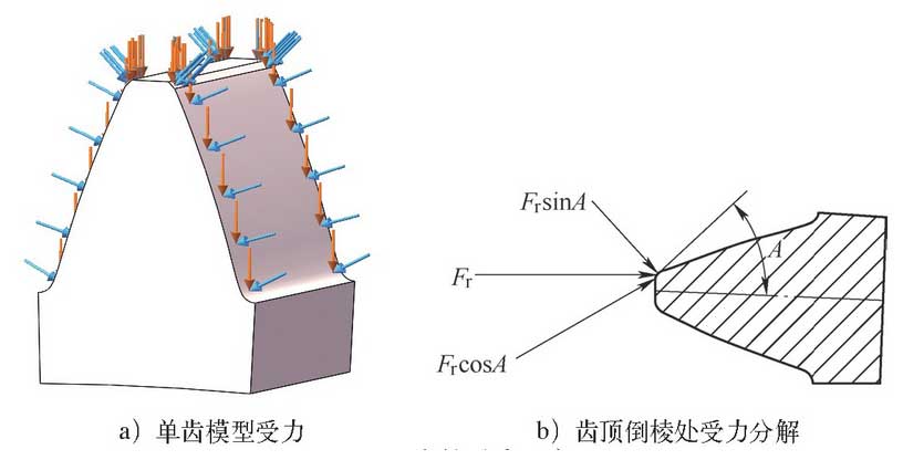
To ensure uniformity of shot peening coverage, the workpiece rotates at a speed VA along the spindle of the machine tool and at a speed VB along the center of the part.According to the movement state of the workpiece, the normal force Fn and radial force Fr are set to act on the tooth surface at the same time. Because the workpiece is symmetrical, a tooth is selected for modeling and simulation.At the chamfer on the top of the tooth, the radial force Fr is decomposed into normal components Frsin A and Frcos A with the chamfer angle A.Qualitatively simulate the stress distribution of tooth surface after being impacted by steel shot. Set the force Fn=100N and Fr=100N uniformly on the tooth surface.
2. Tooth surface stress analysis
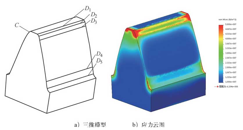
Set the crown circle diameter D1, crown chamfer diameter D2, crown trim diameter D3, involute starting circle diameter D4, root arc starting circle diameter D5, crown chamfer C=0.2m x 45 degrees.The three-dimensional model and stress cloud diagram of a single tooth with top trim are shown in the figure.
Sensors were established at D1, D2, D3, D4 and D5 o f single tooth surface model diameter. The model was modified according to chamfer angle A (30, 45, 60) o f tooth top and flange f K o (20 um, 0 um) o f tooth top respectively. When loading force Fn and Fr were applied, the sensor data at each diameter were summarized as shown in the figure.
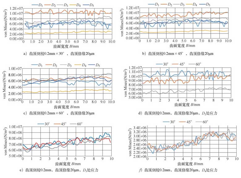
Figures a-c show that the stress at D2 of chamfered part of tooth top is the highest, the stress at D4 of involute initial circle is the lowest, and the stress at D1, D3 and D5 of the remaining parts are similar and centrally distributed; at chamfered angle of 60 degrees, the stress distribution at all parts of tooth surface is relatively uniform and there is no obvious stress concentration; Figure 3d-f shows that the stress at D2 decreases with the increase of chamfered angle, when the chamfered angle increases from 30 degrees toAt 60 degrees, the average stress at D2 decreases by about 40%, D4 decreases by about 5%, other places are relatively stable and have little change; when chamfer angle A increases, the normal component Fsin A of impact force of steel shot increases and tangential component Fcos A decreases, so the chamfer boundary stress decreases.
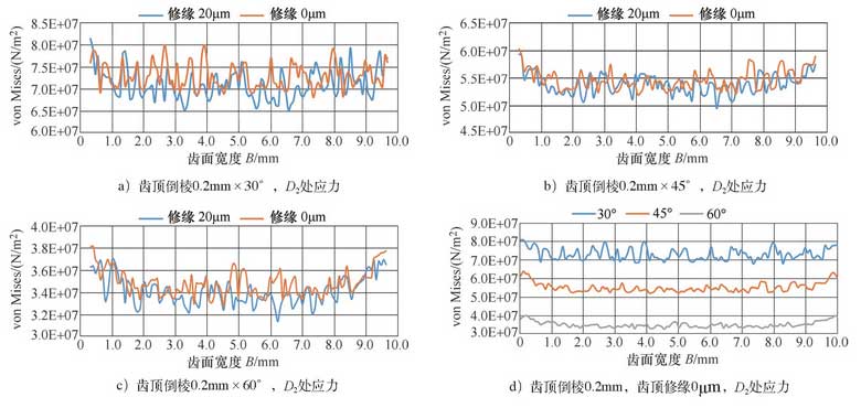
As shown in Figure 4, it can be seen from Figure a to C that the average stress at chamfer D2 is always 5% smaller than that at non-chamfer D2. Figure 4D shows that with the increase of chamfer angle, the stress at chamfer D2 always decreases irrespective of the size of chamfer D2.
It is found from the analysis data that the continuity of the transition of the entire tooth surface, the angle of chamfer and the size of the tip trim edge will affect the stress distribution of the tooth surface. Generally, the stress distribution of the tooth surface shows the following rules: (1) The stress at the beginning D2 of the chamfer with sudden transition of the tooth surface is larger, and the stress at the beginning D4 of the involute is the smallest.(2) With the increase of the chamfer angle, the stress at D2 of the chamfer at the beginning decreases, and the change in other places is not obvious.(3) The stress at D2 of chamfer on top of tooth decreases by about 5% after edge repair.Therefore, the stress concentration at the chamfered edge boundary of the top of the tooth can be reduced by taking the difference in the chamfered angle of the top of the tooth and the difference in the trimming quantity of the top of the tooth.