There are a lot of fault information in the modulation of gear vibration signal, so it is very important to study the signal modulation for gear fault diagnosis. In frequency domain, the result of signal modulation is that the side band component appears around the meshing frequency of gear. Signal modulation can be divided into two types: amplitude modulation and frequency modulation.
Amplitude modulation is caused by the influence of load fluctuation on vibration amplitude. A typical example is that the eccentricity of the gear makes the gear mesh tight and loose at the same time, which results in load fluctuation and makes the amplitude change periodically according to this law. The processing error of gear (such as pitch unevenness) and gear failure make the gear produce transient “loading” and “unloading” effect in meshing, and also produce amplitude modulation.
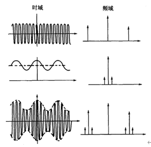
Amplitude modulation is mathematically equivalent to the multiplication of two signals in the time domain and the convolution of two signals in the frequency domain, as shown in Figure 4. One of the two signals is called carrier, and its frequency is relatively high; the other is called modulation wave, and its frequency is relatively low compared with carrier frequency. In the gear signal, the meshing frequency component is usually the carrier component, and the gear shaft rotation frequency component is usually the modulation wave component.

Figure 4 amplitude modulation of single frequency
If XC (T) = asin (2 π FCT + φ) is the vibration signal of gear engagement, and a (T) = 1 + bcos2 π FZT is the rotational frequency vibration signal of gear shaft, the vibration signal after amplitude modulation is
x(t)=A(1+Bcos2πfXt)*sin(2πfct+φ) (1-6)
Where a – is the amplitude;
B – amplitude modulation index;
FZ — modulation frequency, which is equal to the rotation frequency of the gear.
The modulation signal can be expressed as
|x(f)׀=Aδ(f-fc)+1/2ABδ(f-fc-fZ)+1/2AB(f-fc+fZ) (1-7)
It can be seen that in the modulated signal, in addition to the original meshing frequency component, a pair of components (FC + Fz) and (FC Fz) are added. They are symmetrically distributed on both sides with FC as the center and FZ as the spacing, so they are called side band (Figure 1-7)
For the actual gear vibration signal, carrier signal and modulation signal are not single frequency, generally speaking, they are periodic functions. According to formula (1-4), K (T) e 2 (T) can reflect the amplitude modulation caused by fault.
Let y (T) = K (T) E2 (T) (1-8)
Then K (T) is carrier signal, which contains gear meshing frequency and its frequency multiplication component, and E 2 (T) is amplitude modulation signal, reflecting gear error and fault condition. Because the gear runs round and round, E2 (T) changes once every revolution of the gear. E2 (T) contains the rotation frequency of the gear shaft and its frequency doubling component.
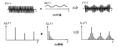
In time domain, y (T) = K (T) E2 (T) (1-9)
In frequency domain, sy (f) = SK (f) * se (f) (1-10)
Where, sy (f), SK (f) and Se (f) are the spectrum of Y (T), K (T) and E2 (T), respectively. Since the carrier signal K (T) and the amplitude modulation signal E2 (T) are multiplied in the time domain, the modulation effect in the frequency domain is equivalent to the convolution of their amplitude spectrum. That is to say, the convolution of a group of pulse functions with larger frequency interval and a group of pulse functions with smaller frequency interval can form several groups of side frequency families around the meshing frequency and its double frequency components on the frequency spectrum (Fig. 5).
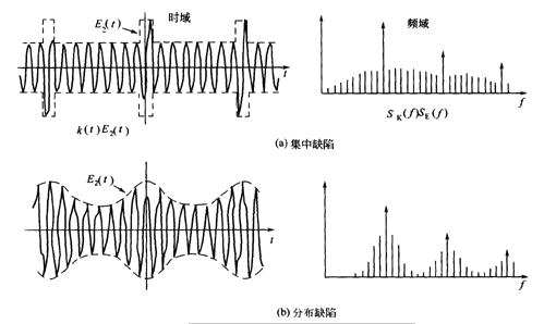
It can explain the difference between the edge frequency caused by concentrated defect and distributed defect. Figure 6 (a) shows the vibration waveform and frequency spectrum when the gear has local defects. At this time, the vibration of the gear is modulated by a short pulse, and the pulse length is equal to the rotation period of the gear. The number of side bands thus formed is large and uniform.
Fig. 6 (b) shows the distribution defects of gears. Because the amplitude modulation caused by distributed defects is relatively gentle, the resulting sideband is relatively high and narrow. Moreover, the more uniform the defect distribution on the gear, the higher and more concentrated the sideband on the spectrum.

Fig. 5 formation of side band on gear spectrum

Fig. 6 Influence of gear defect distribution on sideband
