
The unique geometry and manufacturing processes of hypoid gears grant them exceptional performance in transmitting power between non-intersecting, non-parallel shafts, making them indispensable in automotive drivetrains, particularly for rear axles. While hypoid gears offer significant advantages in torque capacity and design flexibility, their dynamic behavior under various operating conditions is a critical area of study. Issues such as gear whine, vibration, and premature wear, especially during non-driven or lightly loaded conditions, pose significant challenges to durability and noise, vibration, and harshness (NVH) performance. This analysis delves into the dynamic meshing characteristics of a hypoid gear pair, systematically evaluating its performance across different driving scenarios to identify optimal and detrimental operating regimes. The focus is on quantifying dynamic responses through parameters like angular acceleration, transmission error, and structurally radiated noise, providing a data-driven foundation for design optimization aimed at enhanced overall meshing performance.
The core of the investigation revolves around a detailed hypoid gear pair model. The pinion has 11 teeth ($$z_p = 11$$) and the gear has 47 teeth ($$z_g = 47$$), resulting in a ratio of approximately 4.273. A multibody dynamics simulation approach was employed to model the complex interaction. The three-dimensional solid model of the hypoid gear pair was integrated into a dynamic simulation environment. Revolute joints were applied to the pinion and gear shafts to define their rotational degrees of freedom. The contact between the mating tooth flanks was modeled using an impact-based force algorithm, a standard method for simulating collision and continuous contact in mechanical systems. The critical contact parameters defining stiffness, damping, and friction are summarized below.
| Parameter | Value | Parameter | Value |
|---|---|---|---|
| Stiffness Coefficient | 3.16 × 10⁹ N/m | Static Friction Coefficient | 0.08 |
| Damping Coefficient | 5.0 × 10⁴ N·s/m | Dynamic Friction Coefficient | 0.05 |
| Force Exponent | 1.5 | Static Transition Velocity | 0.1 mm/s |
| Penetration Depth | 0.1 mm | Dynamic Transition Velocity | 10 mm/s |
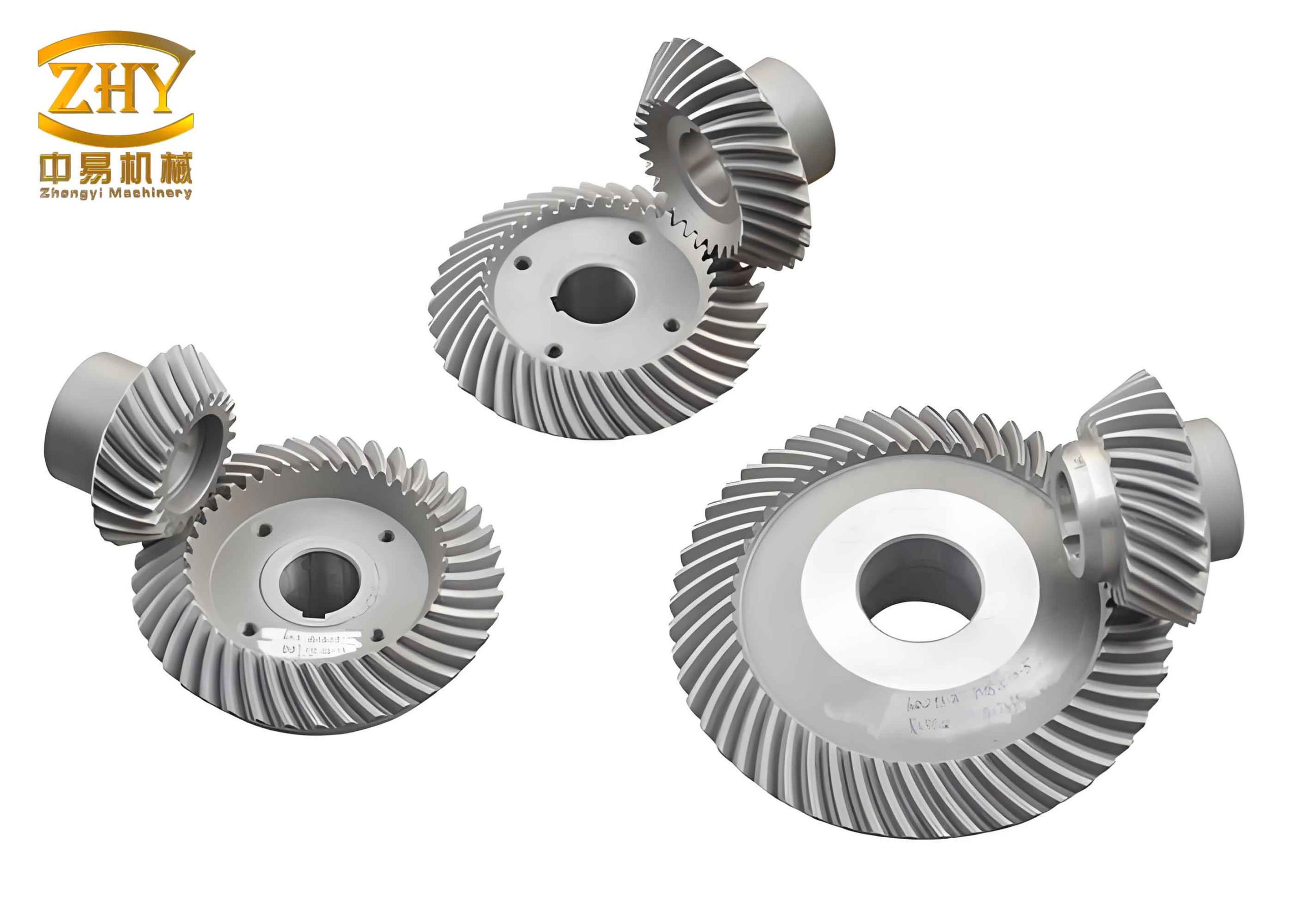
To comprehensively assess the dynamic behavior of the hypoid gear system, four distinct operating conditions were defined, simulating common real-world scenarios in a vehicle application. These conditions vary based on the driving member, the contacting tooth flanks (concave or convex), and the load state.
| Condition Case | Transmission Mode | Driving Flank (Pinion) | Driven Flank (Gear) | Load Torque (kN·m) | Speed (rpm) |
|---|---|---|---|---|---|
| 1 | Forward Drive | Concave | Convex | 1.025 | 1000 |
| 2 | Reverse Drive | Convex | Concave | 1.025 | 1000 |
| 3 | Coast Forward (Neutral) | Gear Concave | Pinion Convex | 0.240 | 234 |
| 4 | Coast Reverse (Neutral) | Gear Convex | Pinion Concave | 0.240 | 234 |
The primary metric for analyzing dynamic excitation is the angular acceleration of the driven member. The time-domain plots for all four cases show oscillatory behavior around zero, indicative of the periodic internal excitations inherent in gear meshing. A key quantitative measure is the root-mean-square (RMS) value of the angular acceleration. For a meaningful comparison between the high-torque drive cases (1 & 2) and the low-torque coast cases (3 & 4), the RMS values for the coast cases were scaled down by the gear ratio (4.273) to reflect equivalent conditions on the input side. The processed data reveals a clear trend.
| Condition | Avg. Ang. Accel. (rad/s²) | RMS Ang. Accel. (rad/s²) | Max Ang. Accel. (rad/s²) | Min Ang. Accel. (rad/s²) | Scaled RMS (rad/s²) |
|---|---|---|---|---|---|
| Forward Drive | 61.29 | 3050.08 | 8040.43 | -13579.53 | 19.41 |
| Reverse Drive | -60.89 | 3279.22 | 973.56 | -11328.16 | 18.75 |
| Coast Forward | -260.63 | 3532.63 | 137040.00 | -50300.81 | 76.58 |
| Coast Reverse | -297.88 | 3987.60 | 66745.65 | -131560.00 | 76.58 |
The scaled RMS values show that the dynamic vibration level, as represented by angular acceleration, is lowest for the Forward Drive condition. The Reverse Drive condition shows a slightly higher level. Critically, the Coast (Neutral) conditions exhibit RMS values approximately four times greater than the drive conditions, indicating significantly more severe dynamic activity and potential for impact and wear during unloaded or lightly loaded operation of the hypoid gear set.
Frequency domain analysis via Fast Fourier Transform (FFT) provides further insight. The fundamental mesh frequency $$f_m$$ is calculated by:
$$ f_m = \frac{N \cdot z}{60} $$
where $$N$$ is the rotational speed in rpm and $$z$$ is the number of teeth of the rotating member. For the pinion at 1000 rpm (Cases 1 & 2), $$f_m = (1000 \times 11) / 60 \approx 183.33$$ Hz. For the gear at 234 rpm (Cases 3 & 4), $$f_m = (234 \times 47) / 60 \approx 183.33$$ Hz. Interestingly, the primary excitation frequency aligns at 183.33 Hz for all cases. However, the spectral content and amplitude differ markedly.
In the Forward Drive case, the highest peak occurs at the fundamental mesh frequency (1x). Significant harmonic content is observed at 3x and 5x the mesh frequency. The Reverse Drive spectrum shows the dominant peak at 2x the mesh frequency, with substantial contributions from 1x, 3x, 4x, and 5x harmonics. The Coast Forward case has its dominant peak at 2x, with notable peaks at 1x and 4x. The Coast Reverse case shows the highest peak at 3x, with strong components at 1x and 2x. Most strikingly, the amplitude of the acceleration peaks in the coast conditions are orders of magnitude larger than those in the drive conditions, confirming the intense vibratory state during neutral operation. This high-level of vibration directly correlates with the audible whine and accelerated wear often reported in such scenarios for hypoid gears.
To further characterize the operational limits of the concave (forward) and convex (reverse) driving flanks of the hypoid gear pinion, a parametric study was conducted under varying loads and speeds. The RMS of the driven gear’s angular acceleration was tracked.
Under a constant speed, the angular acceleration RMS for both driving flanks increases with applied load torque. However, the rate of increase is consistently steeper for the Reverse Drive (convex pinion flank) compared to the Forward Drive (concave pinion flank). Similarly, under a constant load (1.025 kN·m), increasing the driving speed raises the vibration level for both flanks, but again, the Reverse Drive condition exhibits a more sensitive response. This comparative analysis conclusively shows that the concave flank driving mode offers superior dynamic stability and lower vibration excitation across the operating envelope compared to the convex flank driving mode. This inherent asymmetry in the dynamic performance of a hypoid gear pair is a crucial design consideration.
The dynamic forces and accelerations manifest as structurally radiated noise. To evaluate this, the simulated vibration accelerations in both the circumferential (torsional) and radial directions were processed. The acceleration signals were transformed into the frequency domain, and the spectral energy within one-third octave bands centered on the mesh frequency was calculated. The acceleration level $$L_a$$ in decibels (dB) for a given band is defined as:
$$ L_a = 20 \log_{10}\left(\frac{a}{a_0}\right) $$
where $$a$$ is the RMS acceleration (m/s²) within the frequency band, and $$a_0$$ is the reference acceleration ($$1 \times 10^{-6}$$ m/s²). The analysis focused on bands centered at the mesh frequencies for speeds of 800, 1000, and 1200 rpm (146.67, 183.33, and 220.00 Hz, respectively). The acceleration amplitudes extracted from the FFT at these frequencies under different loads are listed below.
| Speed (rpm) / $$f_m$$ (Hz) | Load (kN·m) | Forward Circ. Accel. (10⁻⁴ m/s²) | Forward Radial Accel. (10⁻⁴ m/s²) | Reverse Circ. Accel. (10⁻⁴ m/s²) | Reverse Radial Accel. (10⁻⁴ m/s²) |
|---|---|---|---|---|---|
| 800 / 146.67 | 0 | 3.40 | 4.38 | 3.51 | 4.44 |
| 1.025 | 8.19 | 7.85 | 13.00 | 11.00 | |
| 2.000 | 13.00 | 14.00 | 16.00 | 27.00 | |
| 3.000 | 10.00 | 12.00 | 20.00 | 17.00 | |
| 1000 / 183.33 | 0 | 1.33 | 2.74 | 4.25 | 5.83 |
| 1.025 | 11.00 | 10.00 | 18.00 | 13.00 | |
| 2.000 | 20.00 | 21.00 | 26.00 | 24.00 | |
| 3.000 | 16.00 | 18.00 | 31.00 | 25.00 | |
| 1200 / 220.00 | 0 | 1.61 | 1.89 | 4.43 | 4.06 |
| 1.025 | 14.00 | 13.00 | 21.00 | 16.00 | |
| 2.000 | 30.00 | 32.00 | 38.00 | 37.00 | |
| 3.000 | 25.00 | 26.00 | 45.00 | 39.00 |
Applying the formula for $$L_a$$ to this data reveals consistent trends for the hypoid gear pair. Firstly, for any given combination of speed and load, the calculated noise level for the Reverse Drive condition is invariably higher than that for the Forward Drive condition, in both circumferential and radial directions. This aligns perfectly with the angular acceleration and vibration findings. Secondly, increasing the driving speed leads to a clear increase in noise radiation for both driving modes, as higher meshing impacts generate more vibrational energy. Thirdly, the relationship with load is more nuanced. For a fixed speed, as the load torque increases from no-load to a medium load, the noise level increases due to greater force fluctuations. However, as the load increases further, a slight reduction in noise level is often observed. This can be attributed to increased elastic deformation of the tooth flanks at higher loads, which improves the contact pattern and effective contact ratio, thereby dampening some of the impact forces and mitigating vibration and noise generation in the hypoid gear system.
In conclusion, this dynamic analysis of a hypoid gear pair provides definitive insights into its operational performance. The Forward Drive mode, where the pinion’s concave flank drives the gear’s convex flank, consistently demonstrates the best dynamic performance. It exhibits the lowest levels of angular acceleration fluctuation, the most favorable vibration spectrum, and the lowest structurally radiated noise across various loads and speeds. This establishes it as the optimal condition for primary, sustained power transmission. Conversely, the Reverse Drive mode shows inferior dynamic stability, with higher vibration and noise sensitivity. Most critically, the Coast (Neutral) conditions, characterized by very light loads, exhibit extremely high dynamic excitation levels, explaining the phenomenon of gear whine and severe wear during such operational phases. These findings underscore the critical importance of considering dynamic meshing performance in the design phase of hypoid gears. Design efforts for applications where reverse or coast operation is frequent should focus on optimizing the non-primary drive flanks to mitigate these adverse effects, potentially through localized contact pattern modifications, micro-geometry corrections, or advanced lubrication strategies tailored for the hypoid gear geometry.