
In order to analyze the three-dimensional crack model of helical gear root, a pair of three-dimensional helical gear models need to be parameterized.
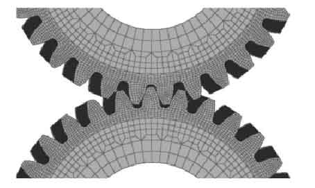
According to the parameters, a pair of correctly meshed gears can be obtained. In order to be more practical and ensure the meshing quality, the gear backlash is 0.1 mm. Mesh the 3D model, as shown in Figure 1.

When establishing the initial three-dimensional crack model, we should first establish the rectangular coordinate system at the tooth root, and then control the established parameters. After creating the initial crack, we should refine the mesh around the crack. The numerical variation of stress intensity factor (SIF) and J-integral (J-integral) of initial cracks with different lengths, loads and positions is discussed. In the comparative simulation, other parameters should be controlled exactly the same, such as gear mesh generation, mesh refinement around the crack, initial influence area of crack establishment and other parameters, so as to better study their variation. Firstly, the coordinate system is established at the center of the tooth root, as shown in Fig. 2 (a), the x-axis is the propagation direction of the crack leading edge, the y-axis is the normal direction of the crack leading edge, and the z-axis is parallel to the crack leading edge; then the parameters of the semi elliptical crack are set to establish its three-dimensional crack, as shown in Fig. 2 (b).