
1 Introduction
Variable angle gearboxes are indispensable support and connection components for transmission lines in aviation systems. At present, domestic and foreign civil aircraft products often use spur bevel gear transmission mechanisms with high manufacturing maturity. Straight cone As the core part of the variable angle gearbox, the wheel is widely used in aviation products such as high lift system and hatch actuation system, and its main function is to change the direction of motion of the transmission line system and transmit torque, etc., while the high lift system of civil aircraft has transmission efficiency, service life and reliability requirements Higher (see Figure 1).
C919 high lift straight bevel gear accuracy and dimensional tolerance requirements are high, especially the contact area is oval, accounting for about 50% of the total tooth length, the contact area position is on the small end, and in order to meet the interchangeability of gear pairs, right Consistency requirements for accuracy, contact area, backlash, and tooth thickness are also high. As an important part of the high lift system of domestic large aircraft, the straight bevel gear of C919 variable angle reducer has been improving its production and processing technology and testing technology.

Fig. 1 C919 High lift spur bevel gear application
2 Research status and development trend at home and abroad
At present, the processing methods of domestic straight bevel gears are mainly divided into precision forging method and cutting method. The precision forging method has low processing accuracy, often only reaching more than 9 grades; The cutting method includes the planing method and the forming tool milling method, etc., the forming tool milling method is suitable for parts with a large modulus, and the common processing method for small module gears is planing teeth. Tooth planing is the use of tooth shape angle equal to the standard pressure angle of the planing tool to cut out the approximate spherical involute, the tooth surface is composed of the spherical center point and the large end tooth profile involute line of each point connection, its contact area can not be modified and is full contact (that is, wire connection Touch).
As shown in Figure 2, the straight bevel gear processed by planing has the following problems: (1) The contact area is in full contact along the tooth length, and edge contact is easy to occur when the gearbox product is assembled; (2) The size and position of the contact zone cannot be accurately controlled, and the contact zone changes with the load; (3) The processing accuracy is low, the tooth surface ripple is large, and the tooth surface wear phenomenon is easy to occur after running-in; (4) The processing consistency is poor and the gear interchange cannot be realized, and the paired grinding delivery is required; (5) Straight bevel gear Missing detection methods or low detection accuracy, such as no CMM tooth surface mesh detection, and low detection accuracy of existing large-end tooth thickness calipers, are the main reasons for the low machining accuracy and poor consistency of gear parts. Line contact straight bevel gear contact is sensitive to installation error and load deformation, and the tooth surface contact area is easy to deviate from the ideal area under actual working conditions to cause eccentric load and edge contact, while tooth surface drum modification can effectively reduce the sensitivity of installation error and load change. Hence the high precision The degree, trimmable and CNC straight bevel gear machining technology can meet the processing of C919 straight bevel gear parts.

Figure 2 Contact area for planing processing
In 2006, Gleason introduced the Coniflex straight bevel gear cutting method (see Figure 3). In 2011, the six-axis five-linkage Phoenix CNC gear milling machine was launched, which was improved from an interlocking tool to a disc-type rotatable cutting tool, and formed a straight bevel gear through a non-hobbing and milling process, which was divided into two upper and lower tools and rolled with the workpiece to form the left and right tooth surfaces respectively. The cutting edge of the tool has a slight angle relative to the plane of rotation, which The combination of inclined cutting edge and tool tilt removes more material at both ends of the cogging, thus forming a longitudinal mismatch of the tooth surface, that is, the tooth surface drum shaped modified tooth machining, so that its contact zone is elliptical or rounded rectangular Local contact.

Figure 3 Coniflex straight bevel gear machining method
The spur bevel gears used in the high-lift variable angle reducer of foreign civil aircraft (such as B737, B787 and A320) are processed by the Coniflex method, and MOOG is the main supplier of straight bevel gears for Boeing and Airbus series models. As the country increases investment in national defense and weapons and equipment, the military industry has developed rapidly and rapidly, and new research models have been increasing. According to statistics, the production demand for spur bevel gears has increased by about 30 times in the past ten years, and there are spur bevel gear transmission mechanisms in more than 30 models. follow With the development and transfer of large civil passenger aircraft into mass production, the production of this type of gear has also continued to increase. In 2018, the market size of the gear industry reached 240 billion yuan[5], of which aviation gears are estimated at around 5 billion yuan, and The straight bevel gear has about 100 million yuan, so the high precision can be repaired straight teeth Bevel gears instead of planing teeth processing is the only way for aviation high-precision gears. The C919 straight bevel gear is also machined using Coniflex CNC milling Tooth processing equipment.
3 Analysis of influencing factors of straight bevel gear machining accuracy
The straight bevel gear is spherical involute, the tooth surface shape is complex, the processing process parameters are not unique, the production and testing are difficult to quantify, and due to the comprehensive influence of various factors, there is a risk that the final surface of the gear cannot meet the product function, and the mutual influence between the various errors of the tooth part, the interchangeability is not high, and the consistency of the tooth surface state is not high. At present, the common straight bevel gear parts materials are 300M, 38CrMoAlA and S82, etc., and the heat treatment is vacuum quenching, carburizing and quenching and tempering respectively. Constrained by the part material, processing method and processing technology, the teeth cannot be sharpened after heat treatment, and the bevel part needs to be processed before heat treatment. The parts will produce thermal deformation after heat treatment, resulting in a decrease in the accuracy of the part, while the carburized parts will have greater deformation. In the absence of finishing such as grinding, stringent requirements are placed on all aspects of the machining process. The machining accuracy error of straight bevel gear mainly comes from the error generated by the machine tool, fixture, tool, tooth blank, manufacturing process, detection accuracy and other processing systems and adjustment processes. Machine tool aspect: After years of processing data statistics, the geometric accuracy of the 275HC CNC gear milling machine can meet GB/T 11365—2019 5 ~ 6 class straight bevel gear milling accuracy. Fixture: Straight bevel gear processing adopts hydraulic gapless positioning fixture clamping, and its positioning accuracy can reach 0. Within 005mm. Tooth billet aspect: Tooth blank tolerance is one of the important factors affecting the manufacturing accuracy of bevel gears, and the definition of tooth blank tolerance is divided into Class I tolerance and Class II tolerance. Class I tolerance is related to the tooth blank datum (such as the tolerance of the outer circle, inner hole and journal), these profiles are not only the bevel gear milling tooth positioning surface but also the detection datum, which directly affects the geometric accuracy of the gear, and can be determined according to the correspondence between the accuracy of the straight bevel gear and the accuracy of the tooth blank Required billet tolerance.
Tools: Tool parameters and tool material machinability and other factors are the main factors that lead to the low machining accuracy of straight bevel gears and the unsatisfactory contact zone, so the core of improvement is the adjustment and correction of the contact area of straight bevel gears. Detection technology: Detection means is a necessary part of high-precision manufacturing of bevel gears, and it is also a prerequisite for high-precision straight bevel gear processing technology support. Process control methods: TCA analysis calculations directly affect straight Contact accuracy of bevel gears. In summary, it can be seen that straight bevel gear milling tools and detection technology are guaranteed Prove that gear accuracy and improve consistency are important factors.
4 Improve the milling tool and improve the machining accuracy of bevel gear
Tool design is an important part of bevel gear processing process control, which directly affects the contact accuracy of straight bevel gear, that is, the size, shape, position and boundary of the contact area.
4.1 Determine the cutter disc angle
The disc angle of the tool δ is the concave angle of the main cutting edge of the disc milling cutter, which forms the drum shape of the machined tooth surface when the disc milling cutter is spread into a tooth surface, and the drum shape affects the size of the contact zone of the bevel gear pair, drum shape
The quantity is obtained from Equation ( 1 ) ~ Equation ( 3). Yes
ρ≈Du /2sinδ ( 1)
Because (ρ - ΔS) 2 + ( B/2) 2 = ρ2 ( 2)
where ρ is the radius of curvature of the bevel tooth line, and the radius of curvature ρ of the bevel tooth line of the straight bevel gear gear is the same as the radius of curvature of the cone surface in the milling cutter; Du is the diameter of the disc milling cutter; δ is the tool disc angle; ΔS is a drum-shaped volume; B is the tooth width of the gear being machined.
4.2 Select the cutterhead diameter
When using Coniflex to machine straight bevel gears, the tool does not move along the cogging length direction, so the length direction of the bottom length of the machined cogging groove is an arc curve, and the tool diameter has a certain relationship with the shape of the drum in the contact area
ΔS≈B2sinδ /4Du ( 3)
It can be seen from Equation (3) that the drum shape ΔS is directly proportional to the width B of the gear to be machined and the recess angle of the main cutting edge of the milling cutter δ, and inversely proportional to the diameter of the milling cutter Du. When the tooth width and cutterhead diameter remain unchanged, the larger the disc angle, the greater the drum shape. The size of the contact zone is related to the drum size ΔS, the drum size is small, the contact area is correspondingly large, the drum size is large, and the contact area is correspondingly small.
4.3 Tool pressure angle
Tool pressure angle, tool disc angle and machine tool shaft angle are related to each other, there are
af = ψ - δ ( 4)
where af is the tool pressure angle; ψ is the knife shaft angle; δ is a knife with a saucer-shaped angle.
4 Tool Wrong Distance (Tool Width)
The tool misalignment (the tip edge width of the tool) is determined by the width of the large end of the cogging bottom and the small end of the gear being machined. The tool error distance needs to meet the condition that it is greater than half of the width of the cogging bottom of the large end and less than the width of the bottom of the cogging of the small end. According to the processing requirements, the bevel gear light load contact zone must be on the small end, need to correct and adjust the contact area, the generated processing program development into the motion trajectory will change, so there will be small end overcut, large end residue or overgouging, is the hidden danger of fatigue failure, each parameter can be calculated as
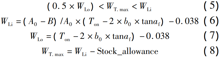
In the formula, WT. max is the maximum knife wrong distance; WLi is small-endian limit cogging width;
WLo is wide, big-endian limit cogging; A0 is the outer taper pitch; B is the tooth surface width;
Ton is the thick of the big-end arc tooth of the matching gear; b0 is the root height of the large end tooth; af is the pressure angle; Stock_allownce is the processing allowance.
Gleason software can only realize the initial design calculation of the tool, and there is no serial specification, resulting in diversified tool specifications, increasing the difficulty of process control and manufacturing costs. To this end, the adjustment principle of tool parameters is summarized, and it is applied according to the relationship between tool parameters and the size and shape of the contact zone The group technology optimizes and improves the tools, develops the reverse verification tool parameter software, reduces the number of tool specifications from 7 sets to 2 sets, and the current tool variety optimization rate reaches 60%. The structure of straight bevel gear cutters is complex, there are many specifications, and the common materials of the tools are mainly powder and metallurgical materials, such as ASP2023 and he ASP2030, TiN, TiAlN and AlCrN are used. Powder metallurgy
Gold tools wear quickly, tooth appearance accuracy is affected by tool wear, there are unstable factors, and the frequency of tool grinding adjustment is relatively high. In the straight bevel gear milling machining, the tool equipped with cemented carbide blade gradually replaces the overall tool of powder metallurgy, and improves the machining of straight bevel gear Precision, higher processing efficiency and more stable quality. Cemented carbide materials have a series of excellent properties such as high hardness and wear resistance, heat resistance, strength and toughness, and are more and more widely used in the cutting process of straight bevel gears. The cutting data, machining accuracy and tool life after tool improvement are shown in Table 1.
Table 1 Comparison of two grade tools
| serial number | content | Powder metallurgy tools | Carbide tools |
| 1 | 转速 | 80 ~ 100r/min | 330 ~ 400r/min |
| 2 | 线速度 | 50 ~ 70m/min | 200m/min |
| 3 | 直齿锥齿轮精度 | GB /T 11365— 2019 的 7 级 | GB/T 11365— 2019 的 5 级 |
| 4 | 齿貌精度 | 0. 01mm | 0. 005mm |
| 5 | 齿面粗糙度 | 1. 1 ~ 1. 4 | 0. 4 ~ 0. 6 |
| 6 | 中点齿厚公差 | 0. 140mm | 0. 025mm |
| 7 | 刀具寿命 | 15 件 | 230 件 |
After improving the tooth milling tool, the machining accuracy of the straight bevel gear is improved from level 7 to level 5 of GB/T 11365—2019, and the tooth appearance accuracy is increased from 0. 01mm raised to 0. 005mm, tooth surface roughness from Ra1. 1 ~1. 4 Boosted to Ra0. 4 ~ 0. 6, so that the contact zone of the straight bevel gear has higher accuracy, the size and position of the contact zone are more accurate, and the tooth surface of the whole circumference is more uniform
And the boundary of the contact area is clearer, which reduces the installation error of the gearbox and the sensitivity of load deformation, and can effectively improve the fatigue strength of the gear. A comparison of the contact zones is shown in Figure 4.

Fig.4 Comparison of the influence of tool improvement on the contact area
5 The influence of detection technology on the machining accuracy of straight bevel gears
5.1 Standard gear
In order to improve the interchangeability of straight bevel gears, standard gears are introduced, and the CMM tooth surface mesh point of this part is set to 0 as a theoretical value for subsequent part machining detection and inversion. Good interchangeability is the main factor in evaluating the accuracy class of standard gears, as shown in Table 2, C919 The standard gear accuracy class used is according to the 5th class of GB/11365-2019.
Table 2 Technical indicators

Straight bevel gear inspection methods and detection accuracy are very important for the manufacturing accuracy of parts, including tooth profile detection, unidirectional accuracy detection, roll detection and midpoint tooth thickness detection.
5.2 Tooth profile CMM detection
Tooth surface detection is an important means of tooth surface shape control, AGMA2009 – B01 specifies the measurement of tooth surface shape in three-dimensional space with a gear measurement center with specific software, compared with a numerically defined theoretical model, and output the results of the relevant topological diagram. The actual and theoretical errors of 5 × 9 tooth surface mesh points were used to evaluate the tooth surface geometry, and domestic scholars solved and meshed in the tooth surface digital model Sun Dianzhu et al., Zhang Junhui et al. used NURBS to construct tooth surfaces for meshing contact analysis, Wang Zhonghou et al. realized the digital solution of involute gear contact spots, and used OpenGL to realize the simulation visualization of contact spots. The tooth surface shape is generated by the contact zone TCA analysis to generate the theoretical value of the mesh point for CMM detection, and the tooth appearance and texture of the processed parts are detected by this program The error between the tooth profiles is discussed and inverted according to the results until the machined parts tend to the theoretical tooth appearance.
The CMM tooth feature tolerance is

where N is the number of teeth; Pd is the large end joint; B is the accuracy class ( AGMA2009 – B01 accuracy).
C919 Straight bevel gear tooth appearance tolerance ± 0. 01mm, in order to make the contact area of the actual processing closer to the theoretical analysis results, the use of cemented carbide tools and high-precision CMM inspection technology, tooth appearance accuracy can be achieved
Up to ± 0. 005mm control, as shown in Figure 5.

Fig. 5 Three-coordinate measurement results of tooth surface shape error
5.3 One-way detection
The single accuracy includes the whole circumferential uniformity of the contact zone of characteristics such as radial runout of ring gear, cumulative deviation of pitch, and limit deviation of gear pitch, and the boundary clarity is affected by radial runout of ring gear, single-cycle deviation and cumulative circumferential deviation The use of cemented carbide tools with high-precision detection technology, the actual machining accuracy can reach the 5th level of GB/T 11365-2019.
5.4 CNC contact area rolling detection and evaluation technology
The detection method of bevel gear contact zone is: bevel gear pair installation distance is fixed, which is used to detect the meshing state of the gear auxiliary tooth surface, evaluate the fit between tooth shapes, evaluate the actual contact of the paired gear from the top of the tooth to the tooth root and along the tooth length, and evaluate the position, size, boundary state and circumferential consistency of the detection contact area. The above tooth morphology and single high accuracy are the basis of the ideal contact zone, and the higher the accuracy, the closer the contact zone is to the TCA theoretical analysis results. The contact zone of the gearbox assembly can only be finalized after the gearbox operating load test. In order to achieve a good contact zone expected by the assembly, the contact area is corrected to the small end according to the test verification law, and the tooth surface has a certain amount of tooth shape and tooth direction modification to make contact The area is oval, which increases the load carrying capacity of the straight bevel gear. The rolling detection accuracy directly affects the evaluation of the contact state of the straight bevel gear, and the high-precision CNC contact area rolling detection is shown in Figure 6, which is one of the important means to ensure the contact accuracy of the straight bevel gear, and it is also one of the conditions for parts to be interchangeable.

Figure 6 NC inspection of the contact area
5.5 Detection of large end backlash and midpoint tooth thickness detection Because the tooth shape tooth is drum-shaped in the direction, the tooth thickness and backlash are only consistent with the theoretical values of the center position of the contact zone, and the large end tooth thickness and backlash need to be re-corrected and calculated according to the contact spot center

In the formula, Bo. cal is the calculated backlash of the big end; Pd is the big-end diameter; d is the diameter of the small wheel; D is the diameter of the large wheel; A0 is the outer taper pitch; x0 is the measured distance from the big end to the center of contact; tcc. MEA is the measured string tooth thickness for the contact center of the small wheel; Tcc. MEA measured chord tooth thickness for the contact center of the large wheel.
Figure 7 shows the effect of contact zone position on tooth thickness and backlash. The backlash of straight bevel gears is a necessary condition for the correct operation of bevel gears, and the most important factor affecting the backlash tolerance is the gear tooth thickness tolerance of phase meshing. In order to To ensure the interchangeability of C919 spur bevel gear parts, the tooth thickness tolerance of the midpoint (i.e. dT point) is strict (only 0.0254mm) and the traditional tooth thickness
The caliper measurement accuracy is 0. Above 1, the tooth thickness tolerance of 0 cannot be met. Inspection requirements for 0254. Use Klingerenberg P65, P40 detectors to detect tooth thickness at dT points on the tooth surface, i.e. the tooth thickness values of specific R and Z points, with an accuracy of 0. 001。 The improved detection accuracy ensures that the machining tolerance of the tooth thickness at the midpoint can reach 0. 025, this accuracy effectively ensures the consistency of straight bevel gear machining and the backlash tolerance of the straight bevel gear pair, which is the second condition for the interchangeability of parts.
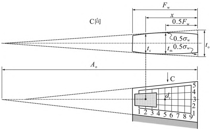
Fig. 7 Influence of contact zone position on tooth thickness and large end backlash
6 Conclusion
In order to meet the processing of straight bevel gear parts of C919 high lift system, the research status of processing technology at home and abroad was analyzed, and after the introduction of CNC drum modified straight bevel gear processing equipment, the straight teeth were affected through research
The influencing factors of bevel gear machining accuracy (especially contact accuracy), under the premise of ensuring the accuracy of tooth blank and fixture accuracy, are improved from the aspects of tool parameters and tool materials, so that the straight bevel gear processing meets the 5-level accuracy of GB/T 11365-2019, the contact zone is oval, the size accounts for about 50% of the tooth length, the contact zone is located at the small end of the tooth length direction, the tooth height direction is centered, and the contact zone boundary is clear, which effectively improves the bearing capacity and fatigue accuracy of the straight bevel gear. Through the study of the corresponding detection technology, the detection accuracy is improved, the tooth profile CMM detection, midpoint tooth thickness detection, CNC contact area rolling detection are realized, and standard gears are introduced to ensure the high precision of straight bevel gears while improving the consistency of processing, especially the accuracy of contact area and backlash, ensuring the interchangeability of straight bevel gears, and changing the status quo of common matching grinding before delivery.