
The MNF file generated in ANSYS is used to replace the ring gear on the wheel hub, that is to build rigid flexible coupling geometry in ADAMS. Considering the influence of backlash on the error of gear transmission, the load mutation of driven gear in the continuous transmission process of two modified helical gears is analyzed, which provides load excitation for the analysis of transient dynamic finite element model. The angular velocity of the input shaft of the gear pair is 3 120 (°) / s, the input power is 8 800 kW, and the reduction ratio is 4.5 ∶ 1. Gear shaft teeth Z1 = 28, modulus Mn = 16, pressure angle α = 20 °, pitch circle helix angle β = 8 °, normal modification coefficient xN1 = 0.211, left-handed; driven teeth Z2 = 126, normal modification coefficient xn2 = 0.163, right-handed. Set simulation time 0.24 s, acceleration time 0.12 s, and total step size of 2400 steps to obtain the angular velocity of gear shaft and driven wheel as shown in Fig. 1; time varying load torque of driven gear is shown in Fig. 2.
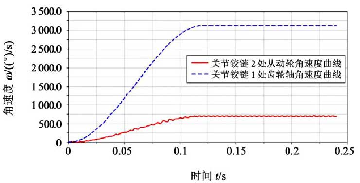
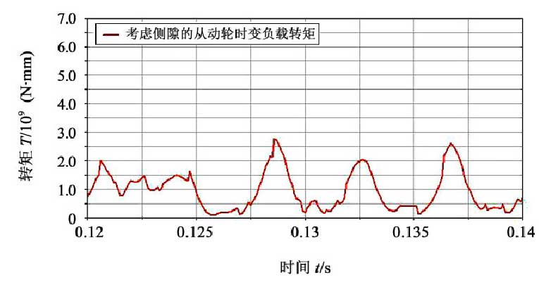
As shown in Fig. 1, the calculated angular velocity of gear shaft is 3 120 (°) / s, that of driven wheel is 693.341 (°) / s, and the reduction ratio is still 4.5 ∶ 1. After the system is stable, the angular velocity still fluctuates, which is caused by transmission error, tooth profile error and meshing impact. It can be seen from Fig. 2 that the sudden load torque on the driven gear shows a certain periodicity, and each pair of wave peaks and troughs is the time required to gradually mesh in and out of the tooth surface, which is consistent with the characteristics of helical gear transmission, indicating the rationality of the model analysis.